
A4 Mk2
| Detaching timing chains from camshafts, removing and installing chain tensioners |

| Special tools and workshop equipment required |
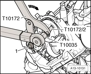
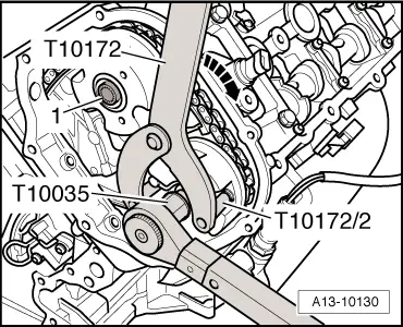
| t | Counterhold tool -T10172- with pin -T10172/2- |
| t | Adapter -T40058- |
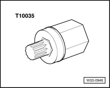
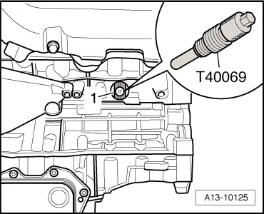
| t | Locking pin -T40069- |
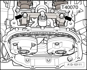
| t | Camshaft clamp -T40070- (2x) |
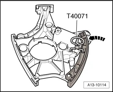
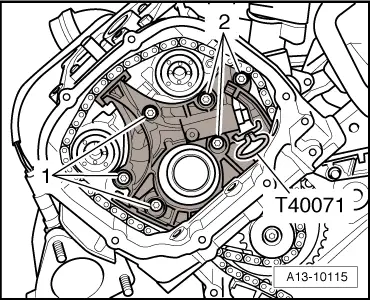
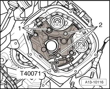
| t | Locking pin -T40071- (2x) |
|
|
 Note
Note
|
|
|
|
|
|
|

|
|

|
|
|
|
|
|
|
|
|
 WARNING
|
|
|
|
|
|
|
|
|
|
|
|
Note
|
|
|
|
|
|
|
|
|
|
|
|
|
|
|
|
|
|
|
|
|
|
|
|
|
|
Note
|
|
|
|
|
|
|
|
|
|
| Component | Nm | ||||||
| Chain tensioner to cylinder head | 9 | ||||||
| Camshaft bolts | 80 + 90° 1)2) | ||||||
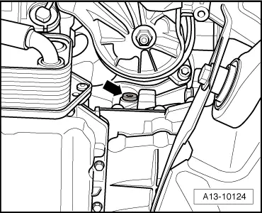
| Screw plug in cylinder block | 14 3) | ||||||
| |||||||