| –
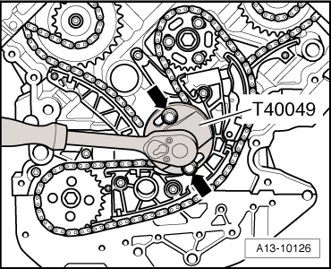
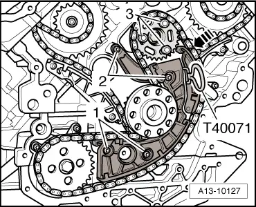
| Install chain tensioner with chain and balance shaft sprocket. |
| –
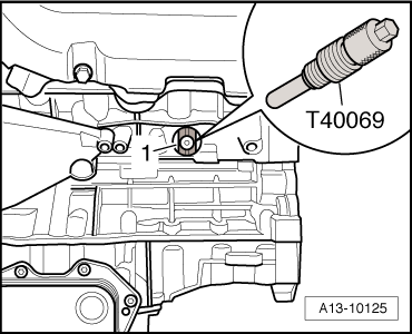
| Wrap insulating tape around tip and shaft of 8 mm Ø drill bit to avoid cuts. |
| –
| Lock balance shaft in TDC position with Ø 8 mm drill bit -item 1-. |
| l
| The elongated holes in the balance shaft sprocket must be aligned centrally over the threaded holes in the balance shaft. If necessary move chain one tooth further. |
| –
| Tighten bolts for chain tensioner. |
| –
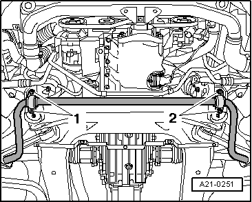
| Screw in bolts -2- for chain sprocket, but do not tighten. |
| l
| It should just be possible to turn the sprocket on the balance shaft without axial movement. |
| –
| Pull locking pin -T40071- out to release chain tensioner. |
| –
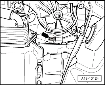
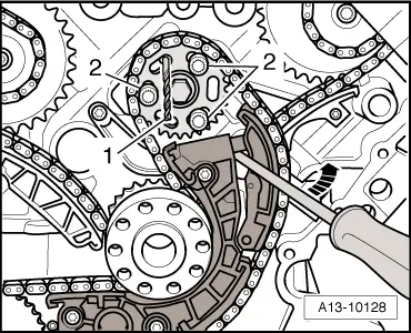
| Press against guide rail of chain tensioner -arrow- using a screwdriver, and at the same time tighten bolts -2- securing chain sprocket. |
| –
| Pull drill bit -item 1- out of balance shaft. |
| Perform further installation in reverse order, paying attention to the following: |
| –
| Install timing chain cover (bottom) → Chapter. |
| –
| Install timing chain covers (left and right) → Chapter. |
| –
| Install crankshaft oil seal (timing chain end) → Chapter. |
| –
| Vehicles with multitronic gearbox: Install flywheel → Chapter and damper unit → Chapter. |
| –
| Vehicles with automatic gearbox: install drive plate → Chapter. |
|
|
|


 Note
Note WARNING
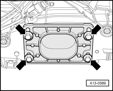
 Caution