
A4 Mk2
| Removing and installing drive chain for valve gear |

| Special tools and workshop equipment required |
| t | Used oil collection and extraction unit -V.A.G 1782- |
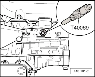
| t | Locking pin -T40069- |
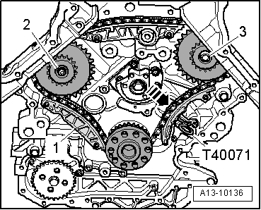
| t | Locking pin -T40071- |
 Note
Note
|
 WARNING
|
|
|
|
|
|
|
|
| Component | Nm | ||||||||
| Drive chain sprocket (left-side) to bearing bracket | 6 + 60° 1)2) | ||||||||
| Drive chain sprocket (right-side) to cylinder block | 30 + 90° 1)3) | ||||||||
| Screw plug in cylinder block | 14 4) | ||||||||
| |||||||||