
A4 Mk2
|
 Note
Note
|
|
 WARNING
Note |
|
|
|
|
|
|
|
Note
|
|
Note
|
|
|
|
 Caution
Note
|
|
|
|
Note
|
|
|
|
|
|
|
|
|
|
|
|
|
|
|
|
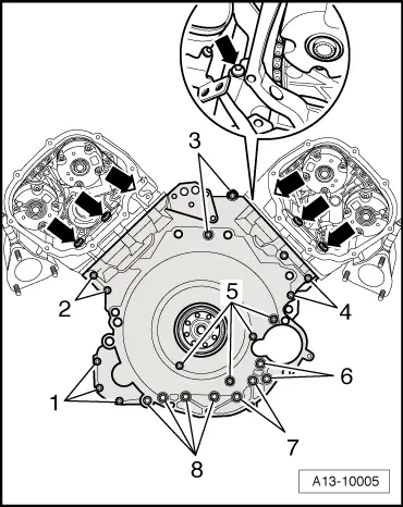
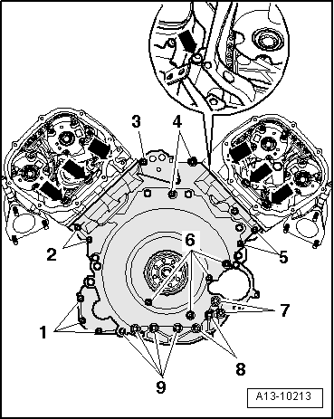
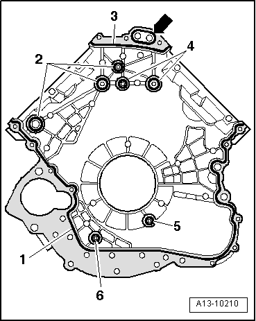
| Component | Nm | |||||||
| Timing chain cover (bottom) to engine | M6 | 9 1) | ||||||
| M7 | 16 | |||||||
| M8 | 20 | |||||||
| Timing chain covers (left and right) to engine | 5 + 90° 2)3) | |||||||
| Bracket for electrical connectors to cylinder head | 9 | |||||||
| ||||||||