
A4 Mk2
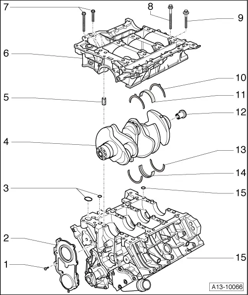
| Crankshaft - exploded view of components |
 Note
Note| When carrying out repairs, secure engine to engine and gearbox support -VAS 6095- → Chapter. |
| 1 - | 9 Nm |
| q | Tighten in stages and in diagonal sequence |
| 2 - | Sealing flange (pulley end) |
| q | Renewing → Chapter |
| 3 - | Seals |
| q | Different versions available → Electronic parts catalogue |
| q | Renew |
| 4 - | Crankshaft |
| q | Measuring axial clearance → Chapter |
| q | Measuring radial clearance → Chapter |
| q | Do not rotate the crankshaft when checking the radial clearance |
| q | Crankshaft dimensions → Chapter |
| 5 - | Dowel sleeve |
| q | 4 x |
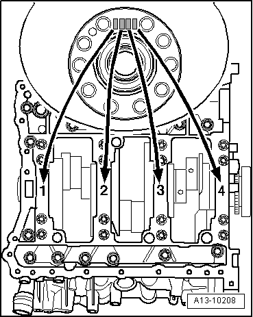
| q | Inserting in retaining frame → Fig. |
| 6 - | Retaining frame |
| q | To remove, detach guide rail → Item for drive chain for valve gear |
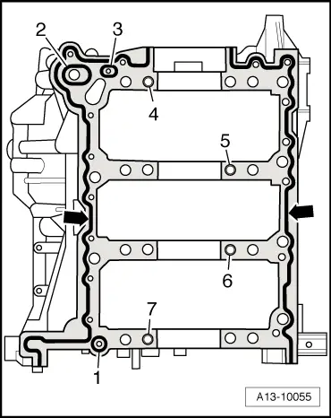
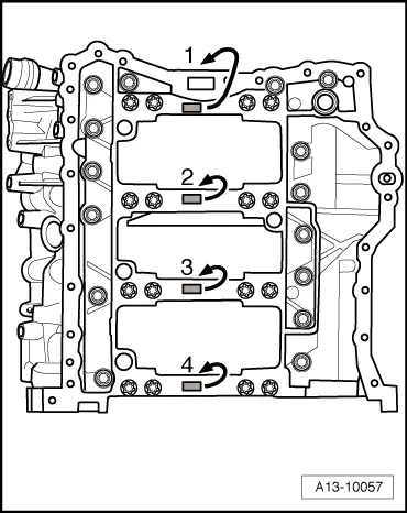
| q | Applying sealant → Fig. |
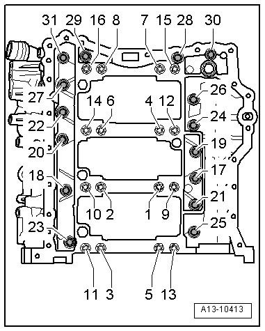
| q | Tightening sequence for securing bolts → Fig. |
| 7 - | Bolt |
| q | For sealing surfaces: cylinder block/retaining frame |
| q | Differing bolt lengths and bolt heads |
| q | Tightening sequence → Fig. |
| 8 - | Bolt (long, large collar) |
| q | For retaining frame (inner row) |
| q | Tightening sequence → Fig. |
| 9 - | Bolt (short, small collar) |
| q | For retaining frame (outer row) |
| q | Tightening sequence → Fig. |
| 10 - | Thrust washer |
| q | Only fitted on 3rd crankshaft bearing |
| q | Oil grooves face outwards |
| q | Make sure it engages in retaining frame |
| q | Measuring axial clearance of crankshaft → Chapter |
| 11 - | Bearing shell |
| q | For retaining frame (without oil groove) |
| q | Do not interchange used bearing shells (mark positions) |
| q | Note installation position |
| q | Install new bearing shells for retaining frame with correct coloured markings → Fig. |
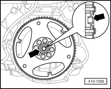
| 12 - | Centralising disc |
| q | For vehicles with automatic gearbox 09L → Fig. |
| 13 - | Thrust washer |
| q | Only fitted on 3rd crankshaft bearing |
| q | Oil grooves face outwards |
| q | Make sure it engages in retaining frame |
| q | Measuring axial clearance of crankshaft → Chapter |
| 14 - | Bearing shell |
| q | For cylinder block (with oil groove) |
| q | Do not interchange used bearing shells (mark positions) |
| q | Note installation position |
| q | Install new bearing shells for the cylinder block with the correct coloured markings → Fig. |
| 15 - | O-ring or seal |
| q | Depending on version → Electronic parts catalogue |
| q | Renew |
| 16 - | Cylinder block |
Note
|
|
|
|
|
|
| Bearing No. | Code letter on retaining frame | Colour coding of bearing | |
| 1 | G | = | Red |
| B | = | Yellow | |
| S | = | Blue | |
| 2 … 4 | G | = | Yellow |
| B | = | Blue | |
| S | = | Black | |
|
| Code letter on retaining frame | Colour coding of bearing | |
| R | = | Red |
| G | = | Yellow |
| B | = | Blue |
| S | = | Black |
|
|
| Bearing No. | Letter on crankshaft | Colour coding of bearing | |
| 1 | G | = | Red |
| B | = | Yellow | |
| S | = | Blue | |
| 2 … 4 | G | = | Yellow |
| B | = | Blue | |
| S | = | Black | |
|
| Letter on crankshaft | Colour coding of bearing | |
| R | = | Red |
| G | = | Yellow |
| B | = | Blue |
| S | = | Black |