
A4 Mk2
| Cylinder head - exploded view of components |
 Note
Note| t | Illustration shows left cylinder head. |
| t | Both cylinder heads can be removed and installed with the engine still installed. |
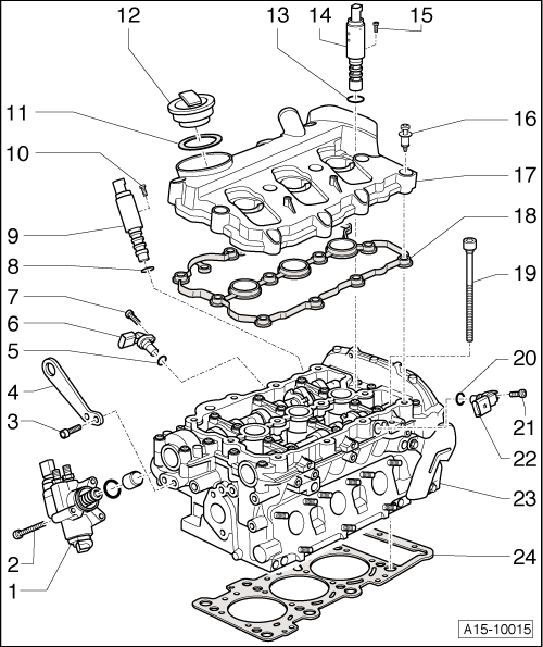
| 1 - | High-pressure pump |
| q | Removing and installing → Rep. Gr.24 |
| 2 - | 9 Nm |
| 3 - | 20 Nm |
| 4 - | Lifting eye |
| 5 - | O-ring |
| q | Renew |
| 6 - | Hall sender for inlet camshaft |
| q | Cylinder bank 1 (right-side) Hall sender -G40- |
| q | Cylinder bank 2 (left-side) Hall sender 2 -G163- |
| 7 - | 8 Nm + 90° (1/4 turn) further |
| q | Renew |
| 8 - | O-ring |
| q | Renew |
| 9 - | Solenoid valve for camshaft control (inlet side) |
| q | Cylinder bank 1 (right-side) camshaft control valve 1 -N205- |
| q | Cylinder bank 2 (left-side) - camshaft control valve 2 -N208- |
| 10 - | 2.5 Nm |
| 11 - | Gasket |
| q | Renew if damaged or leaking |
| 12 - | Filler cap |
| 13 - | O-ring |
| q | Renew |
| 14 - | Solenoid valve for camshaft control (exhaust side) |
| q | Cylinder bank 1 (right-side) - exhaust camshaft control valve 1 -N318- |
| q | Cylinder bank 2 (left-side) - exhaust camshaft control valve 2 -N319- |
| 15 - | 2.5 Nm |
| 16 - | Special bolt, 9 Nm |
| q | Renew if damaged or leaking |
| q | Note correct sequence when tightening → Anchor |
| 17 - | Cylinder head cover |
| q | Removing and installing: left-side → Chapter, right-side → Chapter |
| 18 - | Gasket for cylinder head cover |
| q | Renew if damaged or leaking |
| 19 - | Cylinder head bolt |
| q | Renew |
| q | Note correct sequence when loosening → Anchor |
| q | Note correct sequence when tightening → Anchor |
| 20 - | O-ring |
| q | Renew |
| 21 - | 8 Nm + 90° (1/4 turn) further |
| q | Renew |
| 22 - | Hall sender for exhaust camshaft |
| q | Cylinder bank 1 (right-side) Hall sender 3 -G300- |
| q | Cylinder bank 2 (left-side) Hall sender 4 -G301- |
| 23 - | Cylinder head |
| q | Removing → Chapter |
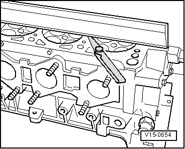
| q | Checking for distortion → Fig. |
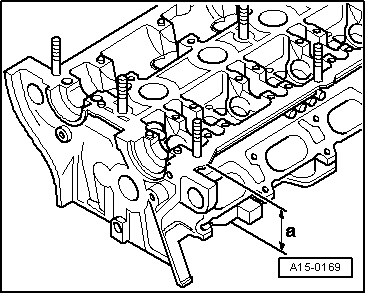
| q | Machining limit → Fig. |
| q | Installing → Anchor |
| q | If renewed, change coolant and engine oil |
| 24 - | Cylinder head gasket |
| q | Renewing → Chapter „Removing and installing cylinder head“ |
| q | Installation position: Part No. towards cylinder head |
| q | If renewed, change coolant and engine oil |
|
|
|
|