audi Workshop Repair Guides

Audi Workshop Service and Repair Manuals

Renewing valve stem oil seals (cylinder head installed) > < Checking axial clearance of camshafts
Removing and installing camshafts
   
Removing and installing camshafts
Special tools and workshop equipment required
t  Impact extractor attachment -T10133/3- from tool set for FSI engines -T10133-
t  Locking pin -T40069-
t  Camshaft clamp -T40070- (2x)
t  Locating pins 1 set = 2x -T40116-
t  Electric drill with plastic brush attachment
t  Safety goggles
t  Sealant → Electronic parts catalogue

Removing
–  Remove cylinder head cover: left-side → Chapter, right-side → Chapter.
–  Remove timing chain covers (left and right) → Chapter.
–  Detach timing chains from camshafts → Chapter.
–  To remove the camshafts (right-side) you must first remove the exhauster pump for brake servo → Chapter.
   
–  Slacken retaining frame bolts in the sequence -22 ... 1-.
  Note
Illustration shows retaining frame of left-side cylinder head.
–  Carefully remove retaining frame.
–  Mark and remove camshafts.
  Note
  A15-10004
To enable the locating pins -T40116- to be attached during installation on engines fitted with dowel pins -arrows- for retaining frame , drive out dowel pins using a suitable drift.
  A10-10871
Installing
  Note
Renew gaskets and seals.
l  Crankshaft -1- locked in position with locking pin -T40069-.
  WARNING
Wear safety goggles.
–  Remove remaining sealant from cylinder head and retaining frame using rotating plastic brush or similar.
  Caution
Make sure that no sealant residue gets into the cylinder head or the bearings.
–  Clean sealing surfaces; they must be free of oil and grease.
–  Lubricate running surfaces of camshafts.
–  Lay retaining frame aside onto workbench, on a soft surface.
  A13-10125
–  Insert camshafts into retaining frame.
l  Camshafts must be in correct position in axial bearings -arrows- in retaining frame.
l  The ends of the piston rings -1- and -2- must point up or down, never to the side.
–  Turn retaining frame upside down with camshafts inserted, keeping hold of the camshafts in the retaining frame.
  A15-10005
–  Turn the camshafts until the threaded holes -arrows- point upwards.
–  Check that camshafts are still in correct position in axial bearings in retaining frame.
  A13-10110
–  Fit camshaft clamp -T40070- as shown in illustration and tighten bolts -arrows- to 20 Nm.
  A13-10111
–  Cut off nozzle of tube at front marking (Ø of nozzle approx. 1 mm).
–  Turn retaining frame back up.
  A17-0081
Vehicles up to approx. 08.2004:
–  Apply the beads of sealant -1 ... 6- onto the clean sealing surfaces of the retaining frame as illustrated.
l  The grooves on the sealing surface must be completely filled with sealant.
l  The beads of sealant must project 1.5 … 2.0 mm above the sealing surface.
  Note
The beads of sealant must be applied exactly according to these instructions, otherwise excess sealant can get into the camshaft bearings.
  A15-10003
Vehicles from approx. 08.2004:
–  Apply a small amount of sealant in groove for gasket -3- in area of opening for camshaft control solenoid valve -arrows-.
–  Press gasket into retaining frame and wipe off excess sealant from gasket and retaining frame.
–  Apply the beads of sealant -1-, -2- and -4- onto the clean sealing surfaces of the retaining frame as illustrated.
l  Width of sealant bead: 1.0 mm.
  Note
The beads of sealant must be applied exactly according to these instructions, otherwise excess sealant can get into the camshaft bearings.
  A15-10192
All vehicles:
  Note
Fit and secure the retaining frame without delay, as the sealant starts hardening immediately.
–  Fit retaining frame onto cylinder head.
–  Insert locating pins -T40116- in retaining frame and cylinder head.
  A10-10819
–  Fit retaining frame onto cylinder head without delay.
–  Tighten retaining frame bolts evenly in the sequence -1 ... 22-, initially only hand-tight.
l  The retaining frame should make contact with the cylinder head over the full surface.
–  Tighten retaining frame bolts to final torque in the sequence -1 ... 22-.
  Note
t  Illustration shows retaining frame of left-side cylinder head.
t  After installing the retaining frame, wait about 30 minutes for the sealant to dry.
  A15-10004
–  Clean bore for sealing plug in cylinder head; it must be free of oil and grease.
–  Coat outer circumference of sealing plug -arrow- with sealant; for sealant refer to → Electronic parts catalogue.
–  Drive in sealing plug until flush.
  A15-10414
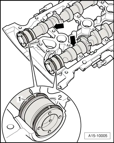
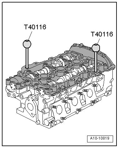
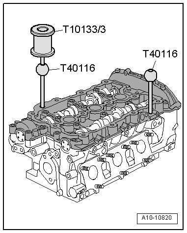
–  Use impact extractor attachment -T10133/3- to pull out locating pins -T40116-.
Perform further installation in reverse order, paying attention to the following:
  Note
t  After installing camshafts, wait for approx. 30 minutes before starting engine. Hydraulic valve compensation elements have to settle (otherwise valves will strike pistons).
t  After working on the valve gear, turn the engine carefully at least 2 rotations by hand to ensure that none of the valves make contact when the starter is operated.
–  Install exhauster pump for brake servo → Chapter.
–  Install camshaft timing chains → Chapter.
–  Install timing chain covers (left and right) → Chapter.
–  Install cylinder head cover: left-side → Chapter, right-side → Chapter.
Tightening torque
  A10-10820
ComponentNm
Retaining frame to cylinder head8 + 90° 1)2)
l  1) Renew bolts.
l  2) 90° = one quarter turn.


Renewing valve stem oil seals (cylinder head installed) > < Checking axial clearance of camshafts