
A4 Mk2
| Removing and installing toothed belt |
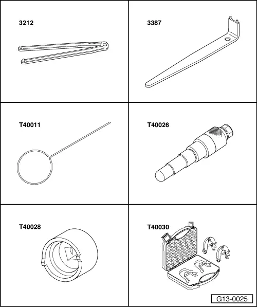
| Special tools and workshop equipment required |
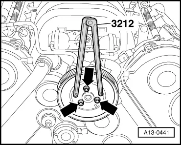
| t | Pin wrench -3212- |
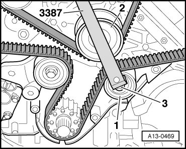
| t | Pin wrench -3387- |
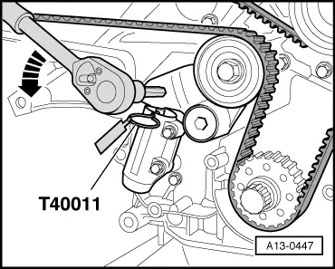
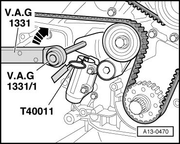
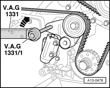
| t | Locking pin -T40011- |
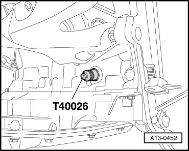
| t | Locking pin -T40026- |
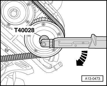
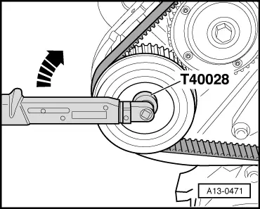
| t | Socket -T40028- |
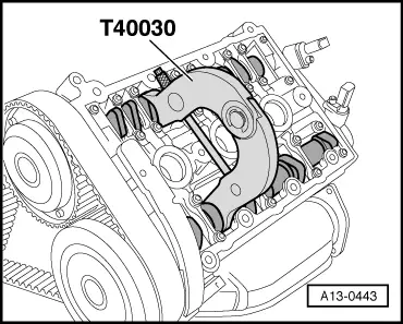
| t | Camshaft clamp -T40030- |
|
|
|
|
|
|
 Note
Note
|
|
|
|
|
|
|
|
|
|
|
|
|
|
|
|
|
|
|
|
 Caution
Note
|
|
Note
|

|
|
|
|
|
Note
|
|
Note
|
|
Note
|
|
|
|
|
|
|
|
|
|
|
|
|
|
|
|
Note
|
|
| Component | Nm |
| Eccentric adjuster to front sealing flange | 45 |
| Camshaft sprocket to camshaft | 100 |
| Sealing plug in cylinder block | 25 |
| Pulley to power steering pump | 23 |