
A4 Mk2
| Removing engine |
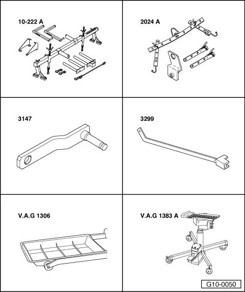
| Special tools and workshop equipment required |
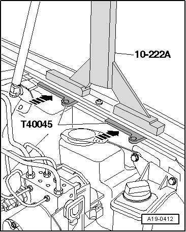
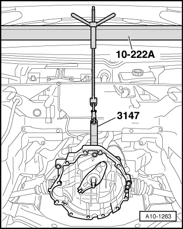
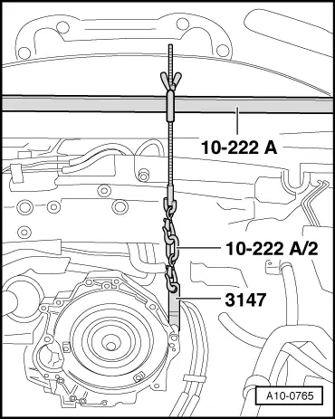
| t | Support bracket -10-222 A- |
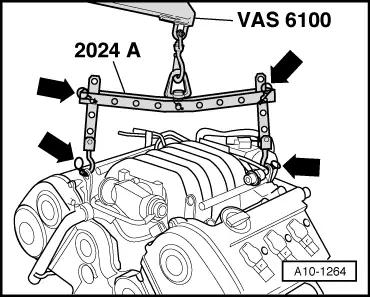
| t | Lifting tackle -2024 A- |
| t | Gearbox support -3147- |
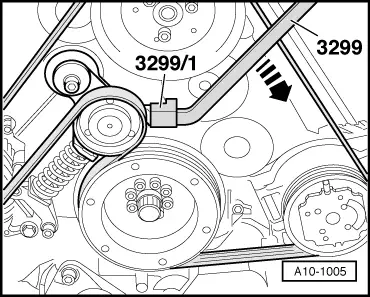
| t | Poly V-belt lever -3299- with bracket -3299/1- |
| t | Drip tray for workshop hoist -VAS 6208- or -V.A.G 1306- |
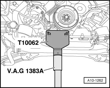
| t | Engine and gearbox jack -V.A.G 1383 A- |

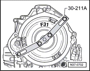
| t | Support bridge -30-211 A- for vehicles with automatic gearbox 01V |
| t | Used oil collection and extraction unit -V.A.G 1782- |
| t | Workshop hoist -VAS 6100- |
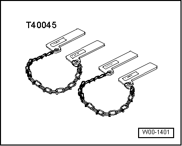
| t | Support -T10062- |
|
|
 Note
Note
|
|
 Caution
|
|
|
|
 WARNING
|
|
|
|
|
|
|
|
|
|
|
|
|
|
Note
|
|
|
|
|
|
|
|
|
|
|
|
|
|
|
|
Note
|
|
|
|
Note
|
|
|
|
|
|
Note
|
|
Note
|
|
|
|
|
|
|
|
|
|
|
|
|
|
|
|
Note |
|
|
|
|
|
|
|
|
|
|
|
|
|
|
|
|
|
|

|
|
|
|
|
Note
|
|
Note
|
|
Note
|
|
Note
|
|
Note |
|
|
|
|
|
Note
|
|
|
|
Note
|
|
|
|
|
|
|
|
Note
|
|
Note
|
|
Note
|
|
Note
|
|
Note |
|
|
|
Note
Note
|
|
Note
|
|
|
|
Note
|
|
Note
|
|
|
|
|
|
Note
|
|
|
|
|
|
Note
|
|
|
|
|
|
Note
|
|
|
|
Note
|
|
Note
Note
Note
|
|
|
|
|
|