
A4 Mk2
 Note
Note
|
 Caution
|
|
|
|
|
|
|
|
|
|
|
|
|
|
Note
|
|
|
|
|
|
|
|
Note
|
|
|
|
|
|
|
|
Note
Note
|

|
| Component | Nm | |
| Intake manifold to cylinder head | 10 | |
| Resonator to coolant pipe / to cylinder head | 10 | |
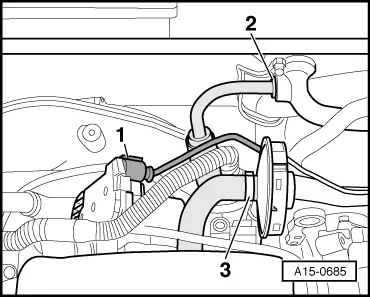
| Secondary air pipe to cylinder head | M6 | 10 |
| M8 | 23 | |
| Secondary air pipe to combination valve for secondary air system | 10 | |
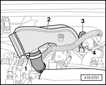
| Air duct to intake manifold | 10 | |
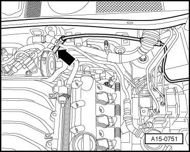
| Retaining plate for solenoid valves to intake manifold / air duct | 10 | |
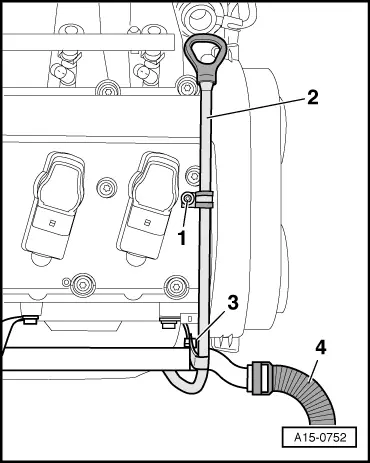
| Guide tube for oil dipstick to secondary air pipe | 10 | |