audi Workshop Repair Guides

Audi Workshop Service and Repair Manuals

Removing and installing front exhaust pipe (left-side) with starter catalytic converter and main catalytic converter on vehicles > < Removing and installing front exhaust pipe (left-side) with starter catalytic converter and main catalytic converter - vehicles
Removing and installing front exhaust pipe (right-side) with starter catalytic converter and main catalytic converter - vehicles with manual gearbox or multitronic gearbox 01J
   
Removing
–  Pull off engine cover panel (rear) -arrows-.
  A10-1032
–  Remove cover -1- at right of engine compartment.
  A10-1030
–  Remove bolts -arrows-.
–  Disengage activated charcoal filter solenoid valve 1 -N80--item 1- at air duct.
–  Remove air duct -2-.
  A10-0900
–  Remove air cleaner housing -arrows-.
  A26-0444
–  Unbolt retaining plate -3- for solenoid valves -arrows-.
–  Detach electrical connector at air mass meter -G70-.
–  Disconnect crankcase breather hose -4- at air duct -2-.
  A34-0460
–  Unscrew bolt -arrow- and pull air duct -2- off throttle valve module -J338-.
–  If fitted, disconnect hose -1- from air duct.
  Note
Shown from rear with engine removed for illustration purposes.
  A34-0461
–  Remove electrical connectors -1 ... 4- from bracket (on right side of bulkhead).
–  Unplug electrical connectors -1- and -4-.
–  Guide wiring for Lambda probes downwards.
  A10-1003
–  Unscrew nut -2- (accessible from above) securing front exhaust pipe to exhaust manifold.
  Note
Shown in illustration with engine removed.
  A26-0440
–  Remove front right wheel.
–  Vehicles with auxiliary heater: remove bolts -arrows- securing exhaust pipe for auxiliary/additional heater to noise insulation.
  A10-0407
–  Release bolts or quick-release fasteners -1- and -2- and take off front noise insulation.
–  If fitted, open quick-release fasteners -3- and remove rear noise insulation.
  A10-1320
–  Unbolt heat shield for drive shaft (right-side) -arrows-.
  Note
  A37-0061
To avoid any damage, the flexible joint in the front exhaust pipe must not be bent more than 10°.
–  Disconnect exhaust system at clamp (right-side) -right arrow-.
  A26-0437
–  Unbolt mounting plate for front exhaust pipe -arrow-.
  A26-0526
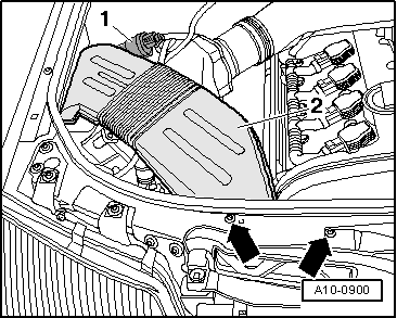
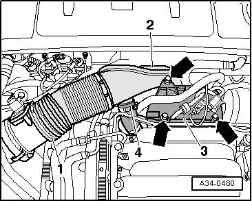
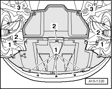
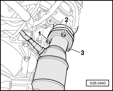
–  Remove nuts -1- and -3- (accessible from below) securing front exhaust pipe to exhaust manifold.
  Note
Shown in illustration with engine removed.
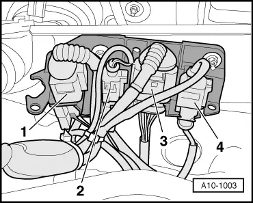
–  Move Lambda probe wires clear.
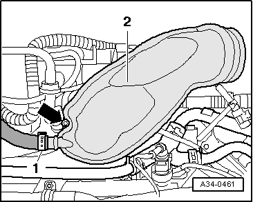
–  Take out front exhaust pipe with starter and main catalytic converter.
Installing
Installation is carried out in the reverse order; note the following:
  Note
t  Renew gaskets and self-locking nuts.
t  
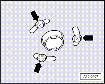
Fit all cable ties in the original positions when installing.
t  When installing, the Lambda probe wires must always be reattached at the same locations to prevent them from coming into contact with the exhaust pipe.
–  Align exhaust system so it is free of stress: vehicles with front-wheel drive → Chapter, vehicles with four-wheel drive → Chapter.
  Note
Components of exhaust system mountings on gearbox: vehicles with manual gearbox and front-wheel drive → Fig., vehicles with manual gearbox and four-wheel drive → Fig., vehicles with multitronic gearbox 01J → Fig..
Tightening torques
  A26-0440
ComponentNm
Front exhaust pipe with starter catalytic converter and main catalytic converter to:Exhaust manifold27
Mounting plate25
Shield for drive shaft to gearbox23


Removing and installing front exhaust pipe (left-side) with starter catalytic converter and main catalytic converter on vehicles > < Removing and installing front exhaust pipe (left-side) with starter catalytic converter and main catalytic converter - vehicles