
A4 Mk2
|
|
|
|
|
|
|
|
|
|
|
 Note
Note
|
|
|
|
|
|
|
|
|
|
Note
|
|
Note
|
|
|
|
Note |
|
|
|
|
|
|
|
|
|
|
|
|
|
Note
|
|
Note
Note
|
|
| Component | Nm | |
| Front exhaust pipe with catalytic converter to: | Exhaust manifold | 27 |
| Mounting plate | 25 | |
| Mounting plate to gearbox | 25 | |
| Lambda probe to catalytic converter | 55 | |
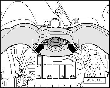
| Engine mounting to console | 23 | |
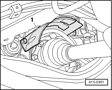
| Drive shaft heat shield to gearbox | 23 | |
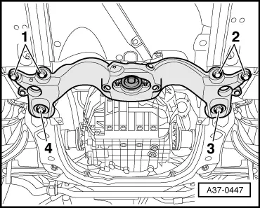
| Front cross member to body | 55 | |