audi Workshop Repair Guides

Audi Workshop Service and Repair Manuals

Removing and installing exhaust manifold (left-side) > < Removing and installing front exhaust pipe (left-side) with catalytic converter - vehicles with automatic gearbox 01V
Removing and installing front exhaust pipe (right-side) with catalytic converter - vehicles with automatic gearbox 01V
Special tools and workshop equipment required
   
t  Lambda probe open ring spanner set -3337-
  W00-0206
t  Engine and gearbox jack -V.A.G 1383 A-
  W00-0120
Removing
–  Pull off engine cover panel (rear) -arrows-.
  A10-1032
–  Remove cover -1- at right of engine compartment.
  A10-1030
–  Remove bolts -arrows-.
–  Disengage activated charcoal filter solenoid valve 1 -N80--item 1- at air duct.
–  Remove air duct -2-.
  A10-0900
–  Remove air cleaner housing -arrows-.
  A26-0444
–  Unbolt retaining plate -3- for solenoid valves -arrows-.
–  Detach air intake hose -1- at air mass meter -G70-.
–  Disconnect crankcase breather hose -4- at air duct -2-.
  A34-0460
–  Unscrew bolt -arrow- and pull air duct -2- off throttle valve module -J338-.
–  If fitted, disconnect hose -1- from air duct.
  Note
Shown from rear with engine removed for illustration purposes.
  A34-0461
–  Remove electrical connectors -1 ... 4- from bracket (on right side of bulkhead).
–  Unplug electrical connectors -1- and -4-.
–  Move electrical wiring to Lambda probes clear.
  A10-1003
–  Unscrew Lambda probe after catalytic converter -G130--arrow- using tool from Lambda probe open ring spanner set -3337/7-.
  Note
Shown in illustration with engine removed.
  A26-0561
–  Unscrew nut -2- (accessible from above) securing front exhaust pipe to exhaust manifold.
  Note
Shown in illustration with engine removed.
  A26-0553
–  Remove front right wheel.
–  Release bolts or quick-release fasteners -1- and -2- and take off front noise insulation.
–  If fitted, open quick-release fasteners -3- and remove rear noise insulation.
  A10-1320
–  Unscrew bolts -1 … 4- and remove front cross-piece.
  Note
  A26-0568
To avoid any damage, the flexible joint in the front exhaust pipe must not be bent more than 10°.
–  Loosen both clamps on exhaust system -arrows- and disconnect exhaust pipes.
  A26-0552
–  Remove heat shield above exhaust system.
–  Remove heat shield for propshaft from cover for Torsen differential -arrows-.
–  Unscrew bolts at gearbox/propshaft flange.
–  Slide propshaft together towards rear final drive; the constant velocity joints can be moved axially
–  Place the propshaft onto exhaust system.
  A34-0122
–  Position lifting column of engine and gearbox jack -V.A.G 1383 A- directly behind rear of ATF oil pan with a piece of wood -1- placed in between.
  Caution
The lock carrier must be installed.
  A37-0528
–  First remove bolts -2- and -3- and then subframe bolts -1- and -4-.
–  Lower gearbox and subframe slowly using engine and gearbox jack -V.A.G 1383 A-.
  A26-0441
–  Unscrew bolts -1 ... 4- for gearbox mounting.
–  Unscrew both gearbox supports -5- and -6- from gearbox housing and remove gearbox supports with gearbox mountings.
–  Carefully lower gearbox.
  A37-0518
–  Unbolt heat shield -1- for drive shaft (right-side).
–  Remove drive shaft (right-side) → Rep. Gr.40.
  A10-0961
–  Unbolt mounting plate for front exhaust pipe -arrow-.
  A26-0443
–  Remove bracket -arrow- for ATF pipes.
  Note
  A37-0500
Observe rules for cleanliness when working on automatic gearbox → Rep. Gr.37.
–  Place drip tray or used oil collection and extraction unit -V.A.G 1782- underneath.
–  Unscrew bolt -arrow- and detach ATF pipes from gearbox.
–  Tie ATF pipes to one side.
  A10-0960
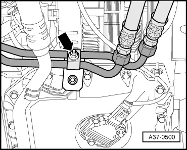
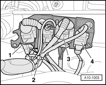
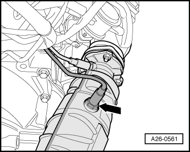
–  Expose Lambda probe wiring.
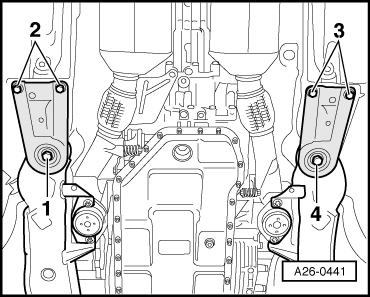
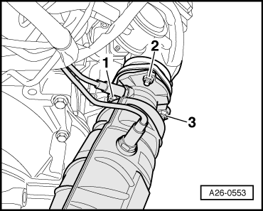
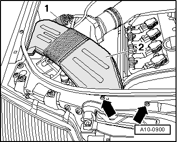
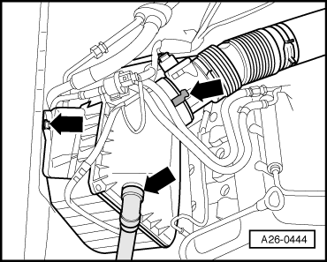
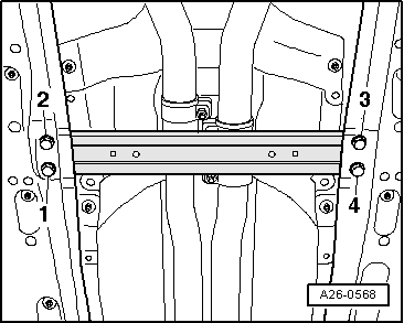
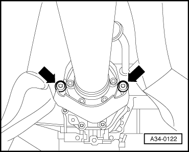
–  Remove nuts -1- and -3- (accessible from below) securing front exhaust pipe to exhaust manifold.
  Note
Shown in illustration with engine removed.
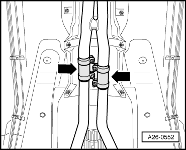
–  Remove front exhaust pipe with catalytic converter.
Installing
Installation is carried out in the reverse order; note the following:
  Note
t  Renew gaskets and self-locking nuts.
t  Threads of new Lambda probes are already greased with assembly paste; the paste must not get into the slots on the probe body
t  When re-using the old Lambda probe, grease thread with high-temperature lubricant; the paste must not get into the slots of the probe body; High-temperature lubricant → Parts catalogue.
t  Fit all cable ties in the original positions when installing.
t  When installing, the Lambda probe wires must always be reattached at the same locations to prevent them from coming into contact with the exhaust pipe.
–  Install gearbox supports → Rep. Gr.37.
–  Install subframe → Rep. Gr.40.
–  Install drive shaft → Rep. Gr.40.
–  Install propshaft → Rep. Gr.39.
–  Secure ATF lines → Rep. Gr.37.
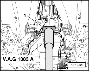
–  Align exhaust system so it is free of stress → Chapter.
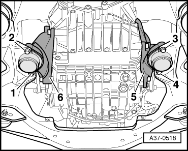
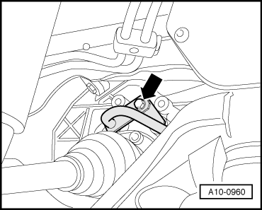
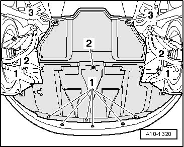
  Note
Components of exhaust pipe mountings on gearbox for vehicles with automatic gearbox 01V → Fig..
–  Check ATF level → Rep. Gr.37.
Tightening torques
  A26-0553
ComponentNm
Front exhaust pipe with catalytic converter to:Exhaust manifold27
Mounting plate25
Mounting plate to gearbox25
Lambda probe to catalytic converter55
Drive shaft heat shield to gearbox23
Front cross member to body55


Removing and installing exhaust manifold (left-side) > < Removing and installing front exhaust pipe (left-side) with catalytic converter - vehicles with automatic gearbox 01V