
A4 Mk2
 Note
Note
|
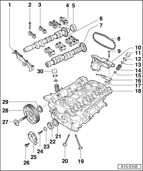
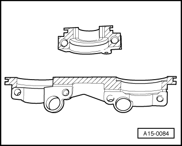
| 1 - | Double bearing cap |
| q | Before installing, coat contact surfaces of front and rear bearing caps lightly with sealant → Fig.; Sealant → Parts catalogue |
| 2 - | 10 Nm |
| 3 - | Bearing cap on exhaust camshaft |
| q | Watch position of dowel sleeve |
| q | Note installation position and allocation → Anchor |
| 4 - | Exhaust camshaft |
| q | Checking axial clearance → Chapter |
| q | Removing and installing → Chapter |
| q | Check radial clearance with Plastigage (bucket tappets removed) |
| q | Radial clearance: wear limit: 0.1 mm |
| q | Runout: max. 0.01 mm |
| 5 - | Cap |
| q | Renewing → Chapter |
| 6 - | Bearing cap on inlet camshaft |
| q | Watch position of dowel sleeve |
| q | Note installation position and allocation → Anchor |
| 7 - | Inlet camshaft |
| q | Checking axial clearance → Chapter |
| q | Removing and installing → Chapter |
| q | Check radial clearance with Plastigage (bucket tappets removed) |
| q | Radial clearance: wear limit: 0.1 mm |
| q | Runout: max. 0.01 mm |
| 8 - | Drive chain |
| q | Installing → Anchor |
| 9 - | 10 Nm |
| 10 - | Mechanical camshaft adjuster |
| q | With inlet camshaft control valve 1 -N205- |
| q | Before removing, lock in position with chain tensioner retainer -3366- → Chapter |
| 11 - | Hydraulic bucket tappet (inlet valve) |
| q | Checking → Chapter |
| q | Removing and installing → Chapter |
| q | Do not interchange (mark allocation) |
| q | Place down with contact surface facing downwards |
| q | Check axial clearance of camshaft before installing → Chapter |
| q | Lubricate contact surface |
| 12 - | Valve cotters |
| 13 - | Valve spring plate |
| 14 - | Valve spring |
| 15 - | Valve stem oil seal |
| q | Renewing → Chapter |
| 16 - | Rubber/metal gasket |
| q | Renew |
| 17 - | Seal |
| q | Renew |
| 18 - | Cylinder head |
| q | See note → Chapter |
| q | Checking valve guides, grinding-in valve seats → Chapter |
| q | Machining valve seats → Chapter |
| 19 - | Exhaust valve |
| q | Do not machine, only grinding-in is permitted |
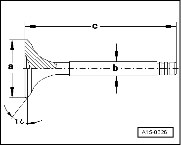
| q | Valve dimensions → Fig. |
| q | Checking valve guides, grinding-in valve seats → Chapter |
| 20 - | Inlet valve |
| q | Do not machine, only grinding-in is permitted |
| q | Valve dimensions → Fig. |
| q | Checking valve guides, grinding-in valve seats → Chapter |
| 21 - | Oil seal |
| q | Note direction of rotation |
| q | Renewing → Chapter and → Chapter |
| 22 - | Rotor for Hall sender |
| q | Note fitting position (notch on camshaft) |
| 23 - | Washer |
| q | Conical |
| 24 - | 25 Nm |
| 25 - | Hall sender |
| 26 - | 10 Nm |
| 27 - | 55 Nm |
| 28 - | Camshaft sprocket |
| 29 - | Oil seal |
| q | Note direction of rotation |
| q | Renewing → Chapter |
| 30 - | Hydraulic bucket tappet (exhaust valve) |
| q | Checking → Chapter |
| q | Removing and installing → Chapter |
| q | Do not interchange (mark allocation) |
| q | Place down with contact surface facing downwards |
| q | Check axial clearance of camshaft before installing → Chapter |
| q | Lubricate contact surface |
Note
|
|
| Dimension | Inlet valve | Exhaust valve | |
| Ø a | mm | 26.80 … 7.00 | 29.80 … 30.00 |
| Ø b | mm | 5.96 … 5.97 | 5.94 … 5.95 |
| c | mm | 104.84 … 105.34 | 103.64 … 104.14 |
| α | ∠° | 45 | 45 |
|
 WARNING
|
|