
A4 Mk2
| Checking secondary air pump relay -J299- and activation |
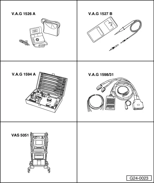
| Special tools and workshop equipment required |
| t | Hand-held multimeter -V.A.G 1526 A- |
| t | Voltage tester -V.A.G 1527 B- |
| t | Auxiliary measuring set -V.A.G 1594 A- |
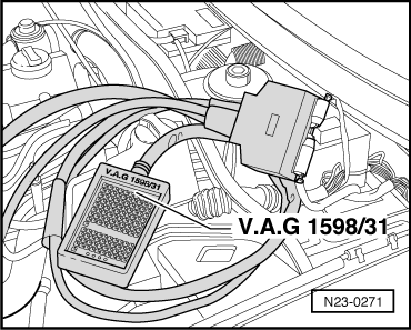
| t | Test box -V.A.G 1598/31- |
| t | Vehicle diagnosis, testing and information system -VAS 5051- |
|
|
|
|
|
|
|
|
|
|
|
|
|
|
|
|
|
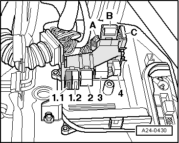
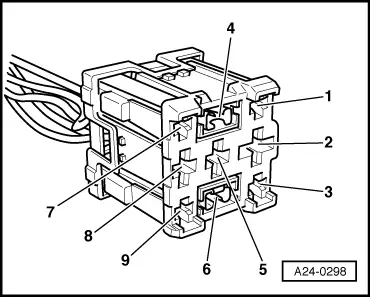
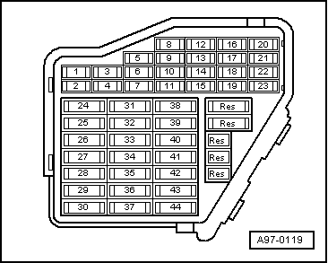
| Relay carrier in plenum chamber electronics box, position 2 Contact | Measure against |
| -8- | Engine earth |
|
|
|
|
|
| Relay carrier in plenum chamber electronics box, position 2 Contact | Measure against |
| -4- | Engine earth |
|
|
|
|
|
| Relay carrier in plenum chamber electronics box, position 2 Contact | Measure against |
| -6- | Engine earth |
|
|
|
|
|
|
| Relay carrier in plenum chamber electronics box, position 2 Contact | Test box -V.A.G 1598/31- Socket |
| -6- | 46 |
|
|
|
|
|
|
|
|
|
|
|