Note | t
| Renew self-locking nuts and bolts when performing assembly work. |
| t
| Renew bolts which are tightened to a specified angle as well as seals, gaskets and O-rings. |
| t
| Hose connections and hoses for charge air system must be free of oil and grease before assembly. |
| t
| To ensure that the charge air hoses can be properly secured at their connections, spray rust remover onto the worm thread of used hose clips before installing. |
| t
| Fit all cable ties in the original positions when installing. |
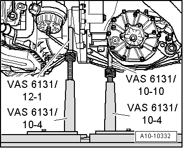
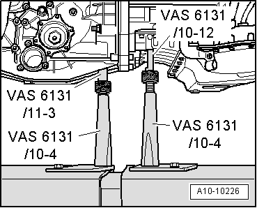
| –
| Install engine supports. |
| –
| When fitting a new clutch plate together with a used pressure plate (self-adjusting clutch), the adjuster ring in the pressure plate has to be reset by turning it back as far as it will go. If this is not done, the pressure plate will operate with reduced clamping force, causing clutch slip → Rep. gr.30. |
Note | t
| If the clutch plate is not being replaced, it is not necessary to reset the adjuster ring. |
| t
| New SAC pressure plates are already pre-set accordingly, and do not have to be reset. |
| –
| Clean input shaft splines and (in the case of used clutch plates) the hub splines. Remove corrosion and apply only a very thin coating of grease for clutch plate splines -G 000 100- to the splines. Do not lubricate guide sleeve. |
| –
| Make sure that clutch plate is properly centred. |
| –
| Check clutch release bearing for wear and make sure that plastic ring is securely seated; renew clutch release bearing if necessary → Rep. gr.30. |
| –
| Check whether dowel sleeves for centring the engine/gearbox assembly are fitted in the cylinder block; install dowel sleeves if necessary. |
| –
| Press intermediate plate between engine and gearbox onto dowel sleeves. |
| –
| Bolt gearbox to engine. |
Note | t
| Tightening torques apply only to lightly greased, oiled, phosphated or black-finished nuts and bolts. |
| t
| Additional lubricants such as engine or gearbox oil may be used, but do not use lubricants containing graphite. |
| t
| Do not use degreased parts. |
| t
| Tolerance for tightening torques: ± 15 %. |
|
|
|

 WARNING
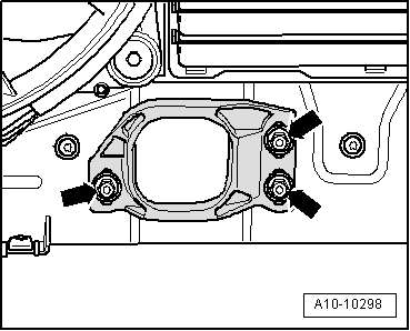
 Caution