
A4 Mk2
|
|
|
 Note
Note
|
|
|
|
|
|
|
|
Note
|
|
|
|
|
|
|
|
|
|
|
|
|
|
|
|
|
|
 WARNING
Note
|
|
|
|
| Component | Nm | ||
| Starter catalytic converter to turbocharger | 27 1)2) | ||
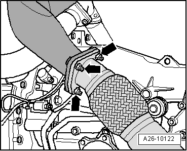
| Heat shield to turbocharger | 9 | ||
| Front exhaust pipe to starter catalytic converter | 25 1) | ||
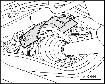
| Drive shaft heat shield to gearbox | 23 | ||
| |||