audi Workshop Repair Guides

Audi Workshop Service and Repair Manuals

Removing and installing coolant pipe (left-side) > < Removing and installing coolant pipe (front)
Removing and installing coolant pipe (rear)
Special tools and workshop equipment required
   
t  Hose clip pliers -VAS 6340-
  W00-10380
Removing
  Note
t  Fit all heat shields and heat insulation sleeves in the original positions when installing.
t  All cable ties which are released or cut open when removing must be fitted in the same position when installing.
–  Drain off coolant → Chapter.
–  Unscrew securing bolts -1- and -5- (bottom) at combination valve for secondary air system (left-side).
  Note
t  Shown in illustration from rear with engine removed.
t  Disregard items marked -2 ... 4-.
  A26-10339
–  Bend heat shield slightly to the side.
–  Unplug electrical connector at engine speed sender -G28--arrow-.
  A28-10010
–  Disconnect coolant hose -arrow- from rear coolant pipe (hose leads to heat exchanger for heater).
  A19-10200
–  Unbolt heat shield -1- for drive shaft (right-side).
–  Unbolt drive shaft from flange shaft on gearbox.
  A10-10417
–  Unscrew securing bolts -4- and -5- (bottom) at combination valve for secondary air system (right-side).
  Note
t  Shown in illustration from rear with engine removed.
t  Disregard items marked -1 ... 3-.
  A26-10340
–  Unplug electrical connector -1- at coolant temperature sender -G62--item 2-.
–  Remove intake manifold → Rep. Gr.24.
–  Take out combination valve for secondary air system (left-side) and lay it aside with vacuum line connected.
  A19-10220
–  Pull off rubber seal and detach plenum chamber cover -1- towards the front -arrows-.
  A27-0088
–  Lever off caps -3- on windscreen wiper arms with a screwdriver.
–  Slacken nuts -4- a few turns.
–  Release wiper arms -2- one by one by tilting them slightly on the wiper shafts.
–  Remove nuts completely and take off wiper arms.
  Note
Use puller (commercially available) to remove wiper arm if necessary.
–  Pull off retaining clips -1- and detach cowl panel trim -5-.
  A20-0833
–  Remove cover for electronics box in plenum chamber -arrows-.
  A10-0996
–  Using a screwdriver, carefully lever out retaining strap -arrow- and remove engine control unit from electronics box.
  Note
The engine control unit remains connected to the wiring harness.
  A10-0997
–  Release retaining hooks -arrows- outwards and remove retaining strap.
  A91-0820
–  Unplug all electrical connectors at connector point -2-.
–  Unscrew electrical wiring -1-.
  A10-1000
–  Release retainers -arrows- and push auxiliary relay carrier in electronics box upwards to remove.
–  Detach the engine wiring harness at electronics box and at bulkhead.
  A10-1001
–  Unplug electrical connectors -1- and -2-.
–  Move electrical wiring harness clear.
–  Place the wiring harness on top of engine and secure the engine control unit to prevent it falling.
  A10-10398
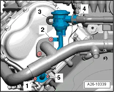
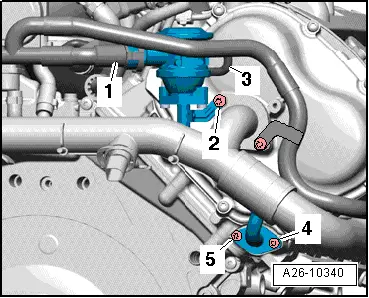
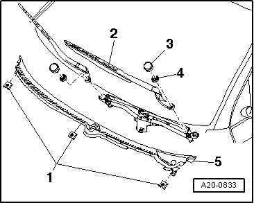
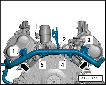
–  Remove bolts -1- and -3-.
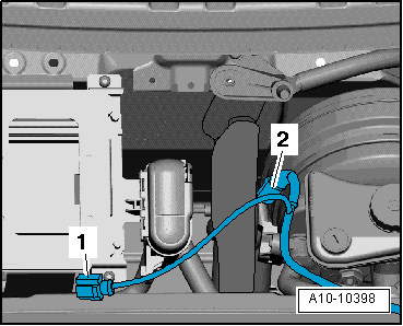
–  Detach coolant hose -2- going to coolant hose/pipe connection.
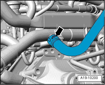
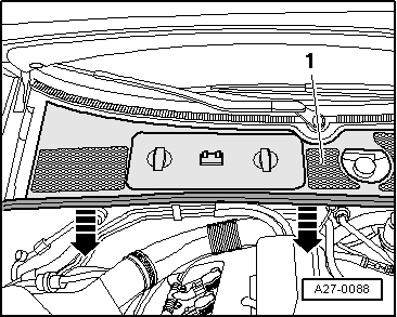
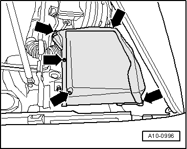
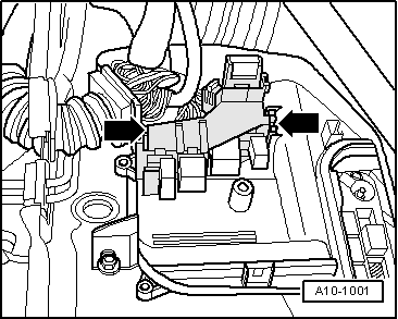
–  Move heat insulation sleeves -arrows- above coolant connecting hoses (right and left) on rear coolant pipe to the side.
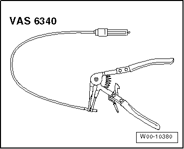
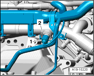
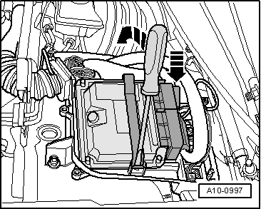
–  Loosen hose clips using spring type clip pliers -VAS 5024 A- and move coolant connecting hoses to the side.
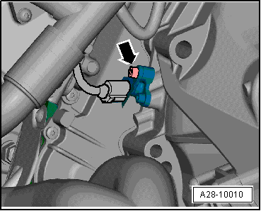
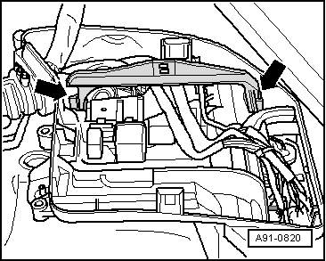
–  Remove electrical connectors -4- and -5- from brackets on coolant pipe (rear).
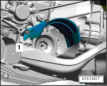
–  Remove coolant pipe (rear) towards the left.
Installing
Installation is carried out in the reverse order; note the following:
  Note
t  Renew O-rings.
t  Secure all hose connections with the correct type of hose clips (same as original equipment) → Electronic parts catalogue.
t  Fit all heat shields and heat insulation sleeves in the original positions when installing.
t  Fit all cable ties in the original positions when installing.
–  Before installing, clean and smooth down sealing surfaces for O-rings as required.
–  Coat new O-rings with acid-free grease (vaseline), fit coolant pipe (rear) and tighten.
–  Install combination valves for secondary air system: left-side → Chapter, right-side → Chapter.
–  Install intake manifold → Rep. Gr.24.
–  Install and adjust wiper arms → Rep. Gr.92.
–  Fill cooling system → Anchor.
Tightening torques
  A19-10221
ComponentNm
Coolant pipe (rear) to cylinder head9
Drive shaft heat shield to gearbox23


Removing and installing coolant pipe (left-side) > < Removing and installing coolant pipe (front)