
A4 Mk2
|
 Note
Note |
|
Note
|
|
|
|
Note
|
|
Note
|
|
|
|
|
|
|
|
|
|
Note
Note |
|
 WARNING
|
|
|
|
Note
|
|
|
|
| Component | Nm |
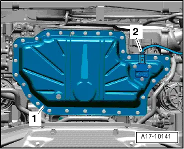
| Sump (top section) to retaining frame | 14 |
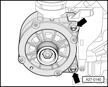
| Bracket for alternator to cylinder block | 22 |
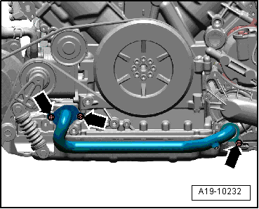
| Tensioner to sump (top section) | 9 |