| –
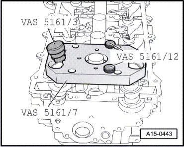
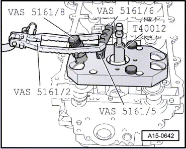
| Insert assembly cartridge -VAS 5161/8- into guide plate -VAS 5161/7-. |
| –
| Press down pressure fork -VAS 5161/2- and pull up knurled screw, thus inserting the valve cotters. |
| –
| Release the pressure fork -VAS 5161/2- with knurled screw still in pulled position. |
| –
| Install camshaft timing chains → Anchor. |
| –
| Install engine: vehicles with manual gearbox → Chapter; vehicles with automatic gearbox → Chapter. |

Note | t
| Engine is not to be rotated for approx. 30 minutes after installing camshafts. Hydraulic valve compensation elements have to settle (otherwise valves will strike pistons). |
| t
| After working on the valve gear, turn the engine carefully at least 2 rotations to ensure that none of the valves make contact when the starter is operated. |
|
|
|