
A4 Mk2
|
 Note
Note
|
|
Note
|
|
|
|
|
|
Note
|
|
|
|
Note
|
|
Note
|
|
|
|
|
|
|
|
|
|
|
|
|
|
Note
|
|
|
|
|
|
|
|
|
|
|
|
Note
|
|
|
|
Note
|
|
|
|
|
|
|
|
|
|
|
|
|
|
Note
|
|
|
|
 WARNING
Note
|
|
|
|
|
|
|
|
|
|
|
|
|
|
|
|
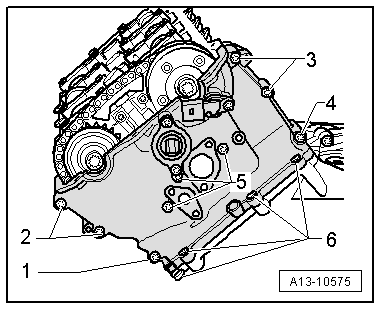
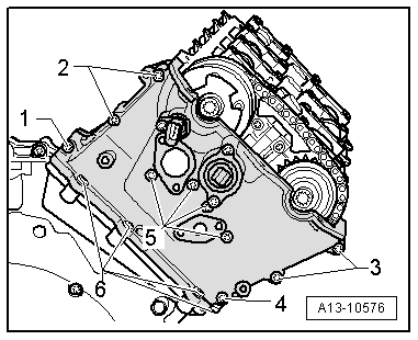
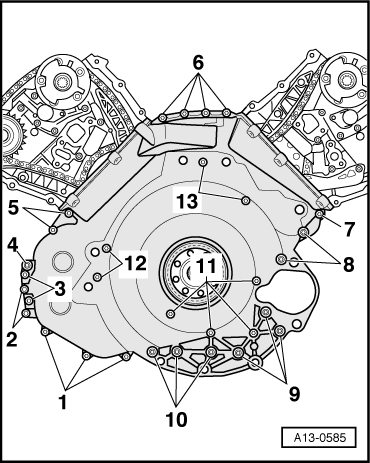
| Component | Nm | ||
| Cover (bottom) | Power steering pump | 22 | |
| For timing chain | Engine | M6 | 10 |
| to: | M8 | 22 | |
| Gasket to timing chain cover | 4 → Note | ||
| Timing chain covers (left and right) to engine | 10 | ||
| Sealing flange to timing chain cover | 10 | ||
| Hall sender to timing chain cover | 10 | ||
| Earth cable to cylinder head | 10 | ||
| Heat shield to engine | 10 | ||
| Oil drain plug | 50 | ||
|