| Removing and installing intake manifold with fuel rail |
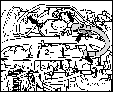
| After the intake manifold has been removed or renewed, intake manifold flap potentiometer -G336- (item 10) must be adapted to the engine control unit -J623-, see vehicle diagnostic and service information system -VAS 5052 A-, “Guided Function” |

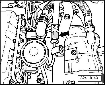
Caution | The fuel pressure must be reduced prior to opening any components in the high-pressure section of the fuel system. It is very important to observe the procedure specified in → Chapter. |
|

Note | t
| The injectors can only be accessed after removal of the intake manifold and fuel rail with air flow control flap. (Additional or fewer steps may be required depending on the model.) |
| t
| The combustion chamber (teflon) ring seal and the O-ring must always be renewed. |
| t
| After the fuel rail has been removed or renewed, intake manifold flap potentiometer -G336- must be adapted to the engine control unit -J623-, see vehicle diagnostic and service information system -VAS 5052 A-, “Guided Function”. |
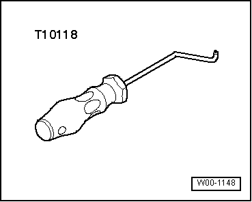
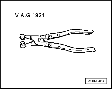
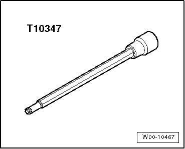
| Special tools and workshop equipment required |
|
|
|