audi Workshop Repair Guides

Audi Workshop Service and Repair Manuals

Servicing tandem pump - vehicles with 4-cylinder engine > < Suction-jet pump: operation
Removing and installing suction-jet pump
Special tools and workshop equipment required
   
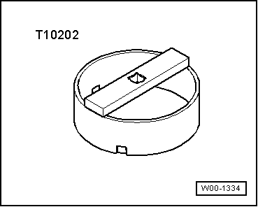
t  Special wrench -T10202-
Removing
Observe safety precautions → Chapter.
Observe rules for cleanliness → Chapter.
l  The fuel tank must not be more than 1/4 full when removing the suction-jet pump. Drain the tank if necessary. Procedure → Chapter.
–  Briefly open filler cap for fuel tank and close again.
  W00-1334
–  Remove rear seat bench → Rep. Gr.72.
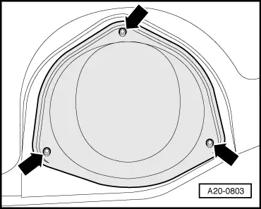
–  Unscrew cover for flange (right-side) -arrows-.
  A20-0803
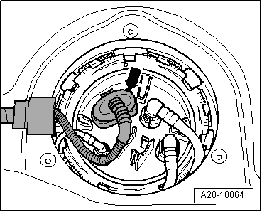
–  Unplug electrical connector -arrow- at flange.
  A20-10064
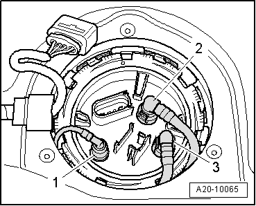
–  Mark fuel return pipe -2- and fuel supply pipe -3-.
  WARNING
The fuel system is pressurised. Before opening the system place a clean cloth around the connection. Then release pressure by carefully loosening the connection.
–  Detach both pipes from flange (press release tabs).
Vehicles with auxiliary heater:
–  In addition, disconnect fuel line -1- leading to metering pump for auxiliary heater by pressing release tab.
  A20-10065
All models:
  Caution
The fuel tank must not be more than 1/4 full when opening the flange. Otherwise a large amount of fuel will escape.
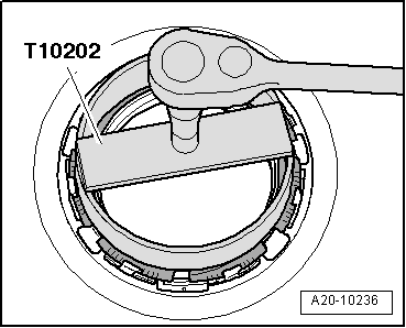
–  Unscrew locking ring using wrench -T10202-.
–  Take flange and seal out of opening in fuel tank and move flange clear, leaving pipes connected.
  A20-10236
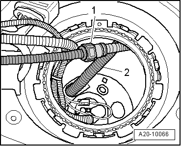
–  Disconnect supply pipe -1- for suction-jet pump by pressing release tab.
–  Disengage fuel supply pipe -2-.
  A20-10066
–  Detach cover for flange (left-side) -arrows-.
  A20-0803
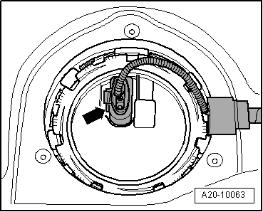
–  Unplug electrical connector -arrow- at flange.
  A20-10063
–  Unscrew locking ring using wrench -T10202-.
–  Remove flange with seal from fuel tank opening.
  A20-10236
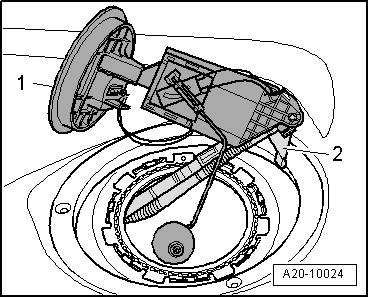
–  Carefully pull flange -1- with fuel gauge sender 2 -G169- and suction-jet pump -2- towards left out of opening in fuel tank.
  Note
When removing, make sure you do not bend float arm of fuel gauge sender 2 -G169-.
Installing
Installation is carried out in the reverse order; note the following:
  Note
t  Renew seals.
t  When installing, make sure you do not bend float arm of fuel gauge sender 2 -G169-.
  A20-10024
–  Push suction-jet pump (with pipes attached) into fuel tank opening on left side of vehicle.
–  Reach into fuel tank opening on right side of vehicle and pull suction-jet pump with pipes into the installation position.
–  Engage fuel supply pipe -2-.
–  Fit supply pipe -1- leading to suction-jet pump so that it engages audibly.
  A20-10066
–  Install new seal for flange (seal must be installed dry).
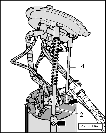
–  Insert guide tubes -1- and -2- for flange in the holes -arrows- in the fuel delivery unit. Make sure that the spring does not slip off the guide tube.
  Note
The fuel delivery unit is shown without the fuel tank for illustration purposes.
  A20-10047
–  Press flange down against spring pressure, and turn flange to installation position.
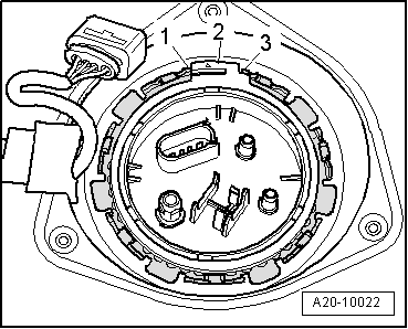
l  Lug -2- on flange must be between tabs -1- and -3- on fuel tank.
  A20-10022
–  Tighten locking ring (right-side).
  A20-10236
–  Install fuel supply pipe -3- and fuel return pipe -2- (as marked).
Vehicles with auxiliary heater:
–  Install fuel line -1- leading to metering pump for auxiliary heater.
All models:
–  Plug in electrical connector.
  A20-10065
–  Install new seal for flange (seal must be installed dry).
–  Press flange down against spring pressure, and turn flange to installation position.
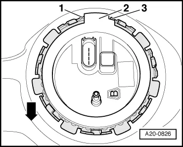
l  Lug -2- on flange must be between tabs -1- and -3- on fuel tank.
  Note
The -arrow- points in direction of travel.
  A20-0826
–  Tighten locking ring (left-side).
  A20-10236
–  Secure cover for flange (left and right side) -arrows-.
–  Put at least 5 litres of fuel into tank after installing fuel delivery unit.
Vehicles with auxiliary heater:
–  Let auxiliary heater run with full load for 10 minutes to bleed fuel supply pipe going to metering pump.
Tightening torque
  A20-0803
ComponentNm
Locking ring for fuel delivery unit or flange of fuel gauge sender 2 -G169-145


Servicing tandem pump - vehicles with 4-cylinder engine > < Suction-jet pump: operation