audi Workshop Repair Guides

Audi Workshop Service and Repair Manuals

Fuel delivery unit, fuel gauge sender - vehicles with front-wheel drive and 2.5 ltr. 6-cylinder engine from 05.2002 onwards > < Checking fuel gauge sender G
Removing and installing fuel gauge senderG
Removing and installing fuel gauge sender -G-
Special tools and workshop equipment required
   
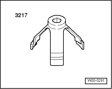
t  Union nut tool -3217-
  W00-0291
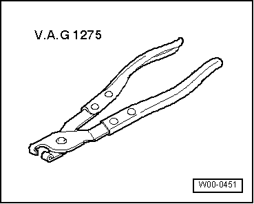
t  Hose clip pliers -V.A.G 1275-
Removing
Observe safety precautions → Chapter.
Observe rules for cleanliness → Chapter.
l  The fuel tank must not be more than 3/4 full when removing fuel gauge sender -G-. Drain the tank if necessary. Procedure → Chapter.
Saloon:
–  Detach trim in luggage compartment.
–  If necessary, fold forward right backrest of rear seat bench.
Avant:
–  Remove left-side section of backrest (1/3 section) → Rep. Gr.72.
–  Remove left-side trim in luggage compartment and anti-soiling tray → Rep. Gr.70.
  W00-0451
All models:
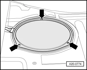
–  Unscrew cover for flange -arrows-.
  A20-0774
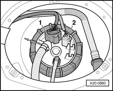
–  Unplug electrical connectors -1- and -2- at flange.
  A20-0880
  WARNING
The fuel system is pressurised. Before opening the system place a clean cloth around the connection. Then release pressure by carefully loosening the connection.
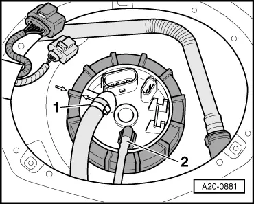
–  Detach fuel supply hose -1- from flange.
–  Detach fuel return pipe -2- from flange (press release tab).
Vehicles with auxiliary heater:
–  In addition, disconnect fuel line leading to metering pump for auxiliary heater (press release tab).
  A20-0881
All models:
  Caution
The fuel tank must not be more than 3/4 full when removing the fuel delivery unit. Otherwise a large amount of fuel will escape.
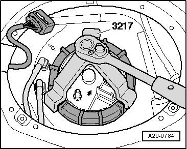
–  Use union nut tool -3217- to unscrew union nut.
  A20-0784
–  Detach flange with seal from fuel tank opening.
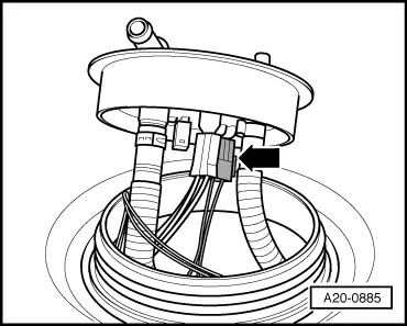
–  Unplug electrical connector -arrow- on inside of flange.
  A20-0885
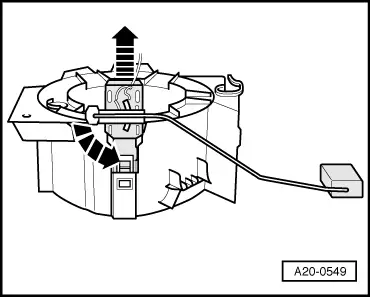
–  Press retaining tab, and at the same time pull fuel gauge sender -G- out of baffle housing guide -arrows-.
  Note
The baffle housing is shown without fuel tank for illustration purposes.
  A20-0549
Installing
Installation is carried out in the reverse order; note the following:
  Note
t  Renew seal.
t  Secure all hose connections with the correct type of hose clips (same as original equipment) → Parts catalogue.
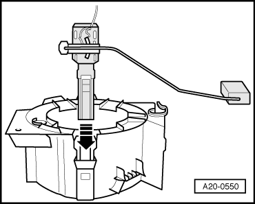
–  Insert fuel gauge sender -G- into guide on outer section of baffle housing and press down until it clicks into place -arrow-.
  A20-0550
–  Attach electrical connector -arrow- to inside of flange.
  A20-0885
–  Install new seal for flange (seal must be installed dry).
–  Move flange to installation position.
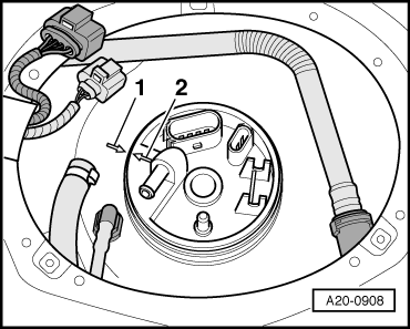
l  Arrow -2- on flange must align with arrow -1- on fuel tank.
  A20-0908
–  Tighten union nut for flange.
  A20-0784
–  Install fuel supply hose -1- and fuel return pipe -2-.
–  Plug in electrical connectors.
Vehicles with auxiliary heater:
–  Let auxiliary heater run with full load for 10 minutes to bleed fuel supply pipe going to metering pump.
Tightening torque
  A20-0881
ComponentNm
Union nut for fuel delivery unit80


Fuel delivery unit, fuel gauge sender - vehicles with front-wheel drive and 2.5 ltr. 6-cylinder engine from 05.2002 onwards > < Checking fuel gauge sender G