audi Workshop Repair Guides

Audi Workshop Service and Repair Manuals

Checking fuel gauge sender G > < Checking fuel pump (electrical test)
Removing and installing fuel delivery unit
Special tools and workshop equipment required
   
t  Special wrench -T10202-
Removing
Observe safety precautions → Chapter.
Observe rules for cleanliness → Chapter.
l  The fuel tank must not be more than 3/4 full when removing the fuel delivery unit. Drain the tank if necessary. Procedure → Chapter.
Saloon:
–  Detach trim in luggage compartment.
–  If necessary, fold forward right backrest of rear seat bench.
Avant:
–  Remove left-side section of backrest (1/3 section) → Rep. Gr.72.
–  Remove left-side trim in luggage compartment and anti-soiling tray → Rep. Gr.70.
  W00-1334
All models:
–  Unscrew cover for flange in luggage compartment -arrows-.
  A20-0774
–  Unplug electrical connector -arrow- at flange.
  A20-10010
–  Mark fuel supply pipe -1- and fuel return pipe -3-.
  WARNING
The fuel system is pressurised. Before opening the system place a clean cloth around the connection. Then release pressure by carefully loosening the connection.
–  Detach both pipes from flange (press release tabs).
Vehicles with auxiliary heater:
–  In addition, disconnect fuel line -2- leading to metering pump for auxiliary heater (press release tab).
  A20-10012
All models:
  Caution
The fuel tank must not be more than 3/4 full when removing the fuel delivery unit. Otherwise a large amount of fuel will escape.
–  Unscrew locking ring using wrench -T10202-.
  A20-10236
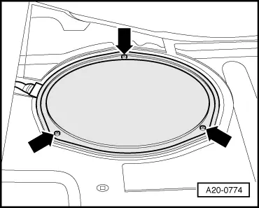
–  Pull fuel delivery unit just slightly out of opening in fuel tank and remove seal.
–  Move flange slightly to one side with fuel delivery unit still located in fuel tank.
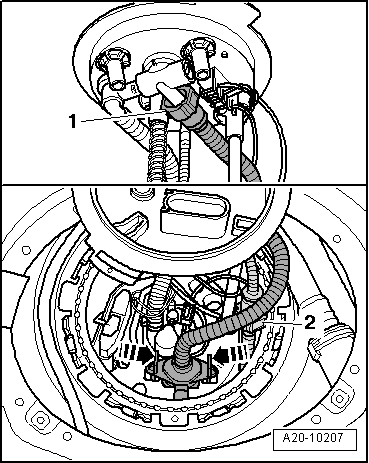
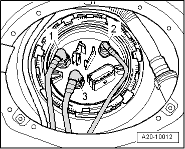
–  On vehicles with auxiliary heater, pull suction pipe -2- for auxiliary heater out of fuel tank and disconnect (press release tab).
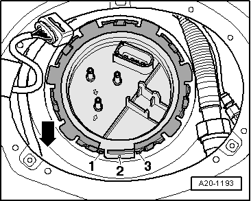
–  Disconnect supply pipe -1- for suction-jet pump on underside of flange by pressing release tab.
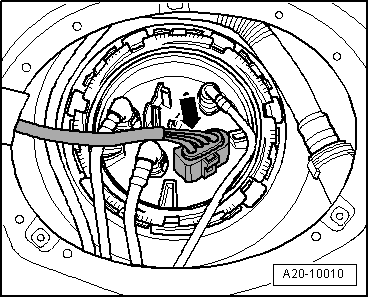
–  Release suction-jet pump -arrows- and remove.
–  Remove fuel delivery unit.
  Note
t  When removing fuel delivery unit, make sure you do not bend float arm of fuel gauge sender -G-.
t  Keep in mind that the fuel delivery unit still contains fuel.
Installing
Installation is carried out in the reverse order; note the following:
  Note
t  Renew seal.
t  When inserting fuel delivery unit, make sure you do not bend float arm of fuel gauge sender -G-.
t  Ensure that fuel hose is securely connected.
  A20-10207
–  Insert fuel delivery unit in fuel tank.
–  Clip suction-jet pump onto fuel delivery unit. To do so, reach into gap between flange and opening in fuel tank.
l  The suction-jet pump should click into place.
–  Check that suction-jet pump has engaged properly.
–  Fit supply pipe -1- leading to suction-jet pump on underside of flange so that it engages audibly.
–  On vehicles with auxiliary heater, fit suction pipe -2- going to auxiliary heater so that it engages audibly.
  A20-10207
–  Install new seal for flange (seal must be installed dry).
–  Press flange down against spring pressure, and turn flange to installation position.
l  Lug -2- on flange must be between tabs -1- and -3- on fuel tank.
  Note
The -arrow- points in direction of travel.
  A20-1193
–  Tighten locking ring.
  A20-10236
–  Install fuel supply pipe -1- and fuel return pipe -3- (as marked).
–  On vehicles with auxiliary heater, install fuel line -2- leading to metering pump for auxiliary heater.
–  Plug in electrical connector.
–  Put at least 5 litres of fuel into tank after installing fuel delivery unit.
Vehicles with auxiliary heater:
–  Let auxiliary heater run with full load for 10 minutes to bleed fuel supply pipe going to metering pump.
Tightening torque
  A20-10012
ComponentNm
Locking ring for fuel delivery unit145


Checking fuel gauge sender G > < Checking fuel pump (electrical test)