| –
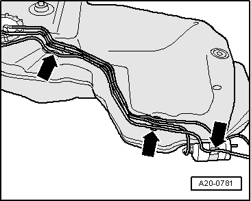
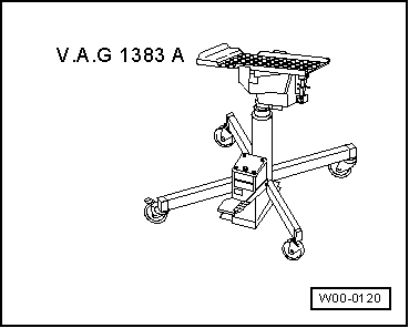
| Position the fuel tank with securing straps on underbody, using the engine and gearbox jack -V.A.G 1383 A-. |
| –
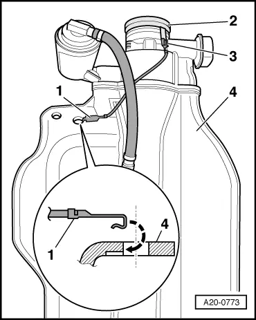
| When installing fuel tank, make sure that the fuel filler neck is correctly inserted into the opening on the body. |
| –
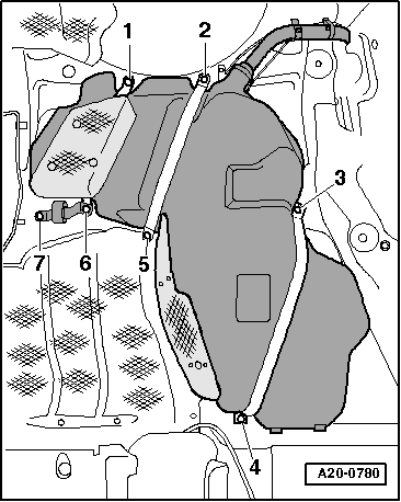
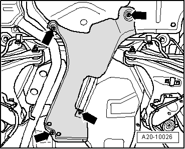
| Secure fuel tank by first tightening bolts at points -2, 5, 3, 4-, then at points -1, 6, 7-. |
| –
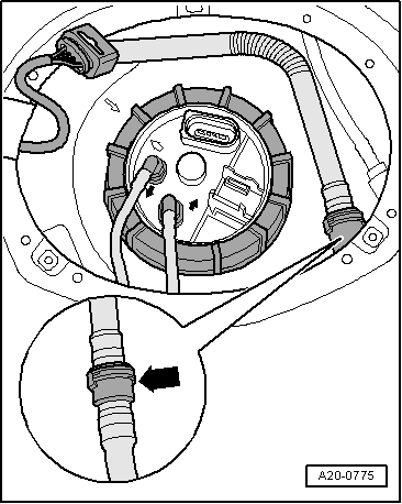
| Secure fuel filler neck. |

Caution | After installation, use an ohmmeter to check the electrical connection between the metal ring on the fuel filler neck and a bare metal part on the body: |
| Specification: approx. 0 Ω. |
|
| –
| Install rear right wheel housing liner and tighten securing bolt for fuel filler neck → Rep. Gr.66. |
| –
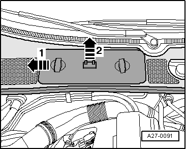
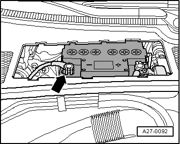
| Connect battery. Observe notes on procedures required after connecting battery → Rep. Gr.27. |
|
|
|

 Note
Note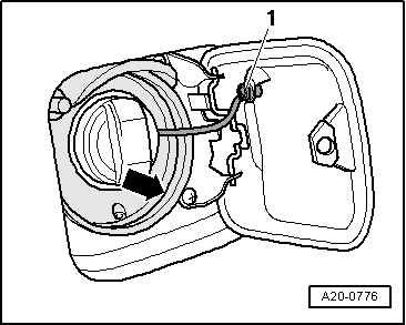
 WARNING