audi Workshop Repair Guides

Audi Workshop Service and Repair Manuals

Checking fuel pump control unit J538 - vehicles with 6-cylinder FSI engine > < Checking fuel pump (electrical test)
Checking fuel pump control unitJ538 - vehicles with 4-cylinder TFSI engine
   
Checking fuel pump control unit -J538- - vehicles with 4-cylinder TFSI engine
Special tools and workshop equipment required
t  Hand-held multimeter -V.A.G 1526C-
t  Auxiliary measuring set -V.A.G 1594C-
t  Adapter cable -V.A.G 1598/39-
t  Test box -V.A.G 1598/42-

   
Procedure
l  Battery voltage at least 12.5 V
l  Fuse in fuse holder -S228- (position 28) OK.
l  Ignition off.
Checking voltage supply for fuel pump (from fuel pump control unit -J538-)
Saloon:
–  Detach trim in luggage compartment.
–  If necessary, fold forward right backrest of rear seat bench.
Avant:
–  Remove left-side section of backrest (1/3 section) → Rep. Gr.72.
–  Remove left-side trim in luggage compartment and anti-soiling tray → Rep. Gr.70.
  A97-0242
All models:
–  Unscrew cover for flange -arrows-.
  A20-0774
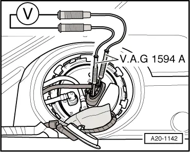
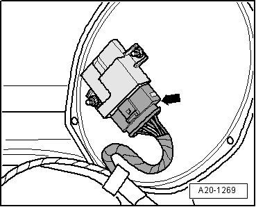
–  Push back protective sleeve.
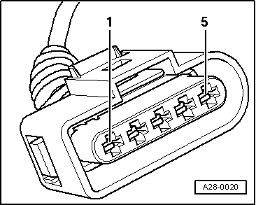
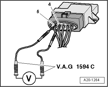
–  Connect hand-held multimeter -V.A.G 1526C- (voltage test range) with probes and plug-in adapters from adapter set -V.A.G 1594C- between contacts -1- and -4-, as shown in illustration; the connector remains in place.
  Note
The connector contacts are numbered accordingly on the back of the connector.
–  Start engine.
l  Specification when starting and at idling speed: approx. 4 ... 5.7 V.
–  Press accelerator pedal quickly to the floor and release again (short throttle burst).
l  Specification: The voltage value should first increase slightly, then drop and eventually rise to the previous reading.
If display differs from specification described above:
–  Check voltage supply and activation of fuel pump control unit -J538-.
  A20-1142
Checking voltage supply for fuel pump control unit -J538-
–  Unplug electrical connector -arrow- on fuel pump control unit -J538-.
  A20-1269
–  Connect multimeter between contacts -3- and -4- of connector to measure voltage.
–  Switch on ignition.
l  Specification: approx. battery voltage
If specification is not obtained:
–  Eliminate open circuit in wiring (refer to current flow diagram).
  A28-0020
Checking activation of fuel pump control unit -J538-
–  Connect multimeter for voltage measurement with measuring probes and plug-in adapters from auxiliary measuring set -V.A.G 1594C- between contacts -4- and -5-, as shown in illustration; the electrical connector remains in place.
  Note
The connector contacts are numbered accordingly on the back of the connector.
–  Start engine.
l  Specification when starting and at idling speed: approx. 5.0 V.
–  Press accelerator pedal quickly to the floor and release again (short throttle burst).
l  Specification: The voltage value should first increase slightly, then drop and eventually rise to the previous reading.
  A20-1264
If display differs from specification described above:
–  Switch off ignition.
–  Connect the test box -V.A.G 1598/42- to wiring harness with adapter lead -V.A.G 1598/39-1- or adapter lead -V.A.G 1598/39-2-. Do not connect engine control unit. Connect earth clip of test box to negative terminal of battery → Rep. Gr.24.
  Caution
To prevent damage to electronic components, select appropriate measuring range before connecting measuring leads and observe test requirements.
  A24-0622
–  Check for open circuit and short to positive or earth in the following wiring:
  A28-0020
Connector
Contact
-V.A.G 1598/42-
Socket
-5-B 27

–  Repair open circuit or short circuit in wiring (refer to current flow diagram).
If no fault is found:
–  Renew fuel pump control unit -J538-.
   

Checking fuel pump control unit J538 - vehicles with 6-cylinder FSI engine > < Checking fuel pump (electrical test)