
A4 Mk2
|
|
|
|
|
|
|
|
|
|
|
|
|
|
|
|
|
|
|
|
|
|
|
 WARNING
|
|
 Note
Note
|
|
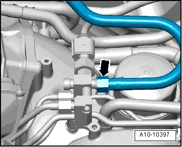
| Component | Nm | |
| Fuel line to fuel rail | 28 | |