A4 Mk2
| Fuel tank with components - exploded view |
 Note
Note| The illustration shows a fuel system without fuel return pipe. |
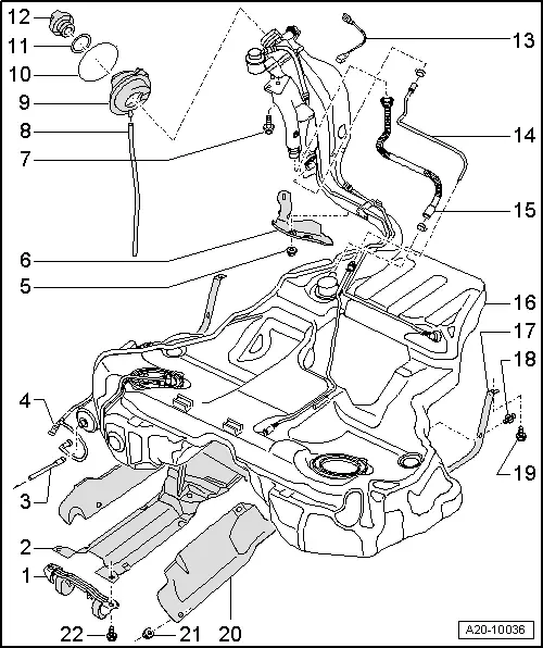
| 1 - | Bracket for exhaust system |
| 2 - | Support bracket |
| 3 - | Fuel pipe |
| q | From fuel filter |
| q | To engine |
| q | Do not kink |
| q | Press release tab on pipe connector to disconnect |
| 4 - | Breather pipe |
| q | Leading to activated charcoal filter in wheel housing (front right) |
| q | Do not kink |
| q | Press release tab on pipe connector to disconnect |
| q | Clip onto fuel tank |
| 5 - | 2 Nm |
| 6 - | Heat shield |
| q | For fuel filler neck |
| 7 - | 23 Nm |
| q | Secures fuel filler neck and earth connection → Item |
| 8 - | Overflow hose |
| 9 - | Rubber cup |
| 10 - | Retaining ring |
| 11 - | Seal |
| q | Renew if damaged |
| 12 - | Filler cap |
| q | Secured to tank flap |
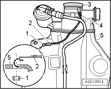
| 13 - | Earth connection |
| q | To eliminate electrostatic charge |
| q | Installation position / test procedure → Fig. |
| q | Ensure that connector is seated properly and secure wire with securing bolt for fuel filler neck → Item |
| q | After installation, use an ohmmeter to check the electrical connection between the metal ring on the fuel filler neck and a bare metal part on the body. Specification: approx. 0 Ω |
| 14 - | Breather pipe |
| 15 - | Breather pipe |
| 16 - | Fuel tank |
| q | Removing and installing → Chapter |
| 17 - | Securing strap |
| 18 - | Spreader clip |
| 19 - | 23 Nm |
| 20 - | Heat shield |
| q | For fuel tank |
| 21 - | 2 Nm |
| 22 - | 23 Nm |
 Caution