audi Workshop Repair Guides

Audi Workshop Service and Repair Manuals

Exploded view of fitting locations Engine code letters: ASN, BBJ > < Technical data
Motronic injection and ignition system (6-cyl.)
Servicing Motronic injection system
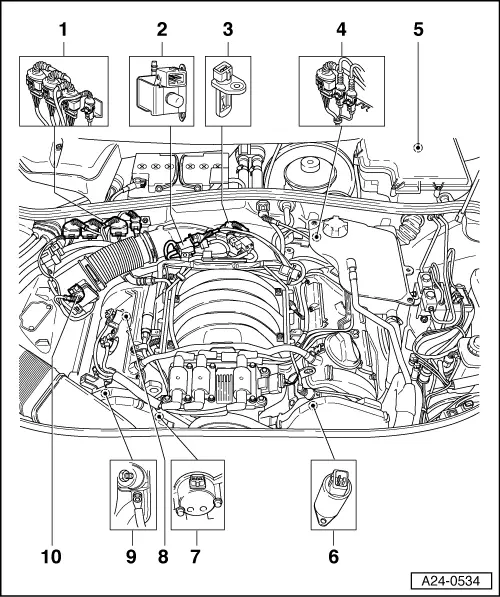
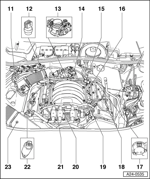
Exploded view of fitting locations Engine code letters: AMM, BDV

Components A to D are not illustrated in the exploded view.

  •     A -    Accelerator position sender -G79 and accelerator pedal position sender 2 -G185
    • ◆ Fitting location
      => Fig. 24-22
  •     B -    Brake light switch -F and brake pedal switch -F47
    • ◆ Fitting location
      => Fig. 24-23
  •     C -    Clutch pedal switch -F36
    • ◆ Fitting location
      => Fig. 24-23
  •     D -    Engine control unit and relays in plenum chamber electronics box
    • ◆ Fitting locations
      =>Fig. 24-24
 
A24-0534
  • Holder for connectors
    • ◆ For right side of vehicle
    • ◆ Assignment
      => Fig. 24-24
  • Secondary air inlet valve -N112
  • Intake-air temperature sender -G42
  • Holder for connectors
    • ◆ For left side of vehicle
    • ◆ Assignment
      => Fig. 24-25
  • Electronics box in plenum chamber
    • ◆ Fitting locations
      => Fig. 24-24
 
A24-0534
  • Camshaft adjustment valve 2 -N208
  • Hall sender -G40
    • ◆ Bank 1
  • Lambda probe -G39 and Lambda probe heater -Z19
    • ◆ Bank 1, probe 1
  • Earth connection
    • ◆ At engine support on right
  • Air-mass meter -G70
 
A24-0535
  • Activated charcoal filter solenoid valve -N80
  • Coolant temperature sender -G62
    • ◆ With coolant temperature sender -G2
    • ◆ For engine control unit
    • ◆ At coolant pipe behind cylinder head, bank 1
    • ◆ Dissipate cooling system pressure if necessary prior to removal
  • Throttle valve control part -J338
    • ◆ With throttle valve drive -G186, throttle valve drive angle sender 1 -G187 and throttle valve drive angle sender 2 -G188
 
A24-0535
  • Intake manifold changeover valve
    -N156
  • Fuel pressure regulator
  • Engine speed sender -G28
    • ◆ In gearbox housing above ring gear
  • Hall sender 2 -G163
    • ◆ Bank 2
  • Lambda probe 2 -G108 and Lambda probe 2 heater -Z28
    • ◆ Bank 2, probe 1
  • Knock sensor 2 -G66
  • Ignition coil -N, ignition coil 2 -N128, ignition coil 3 -N158
    • ◆ With final output stage-N122
 
A24-0535
  • Knock sensor 1 -G61
  • Camshaft adjustment valve 1 -N205
  • Secondary air pump motor -V101

Exploded view of fitting locations Engine code letters: ASN, BBJ > < Technical data