
A4 Mk2
|
Servicing Motronic injection system
Replacing engine control unit
The following procedure applies to engine control units which are not bolted to a sheet-metal housing (to prevent theft). For procedure for engine control units with sheet-metal housing, refer to =>Page 24-40. Removing |
 |
|
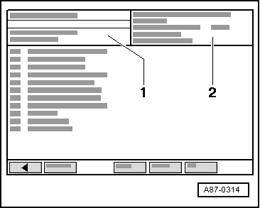
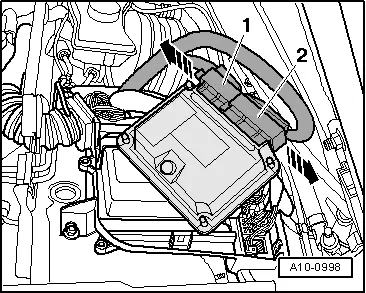
→ Control unit identification and code -2- appear on display of vehicle diagnostic, testing and information system VAS 5051.
|
 |
|
|
 |
|
|
 |
|
|
 |
|
|
|
|
→ Control unit identification and code -2- appear on display of vehicle diagnostic, testing and information system VAS 5051.
|
|
|
|
|
|
|
|
|
|
 |
|
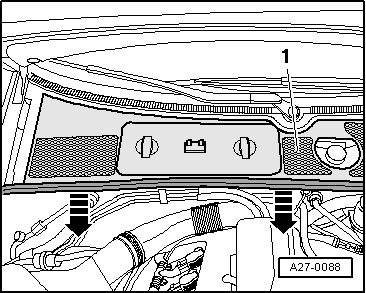
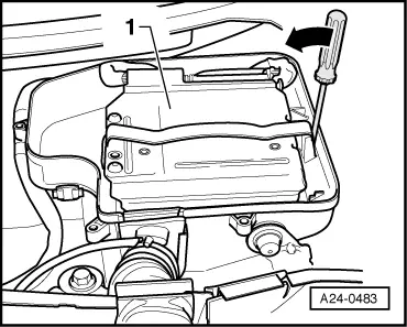
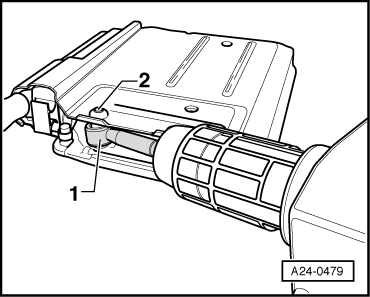
Note: Item -1- in illustration shows engine control unit with anti-theft housing. |
 |
|
|
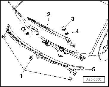
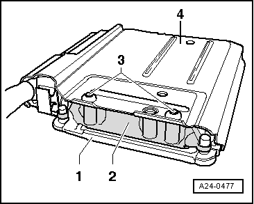
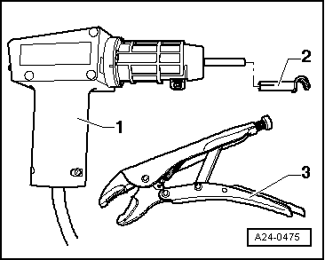
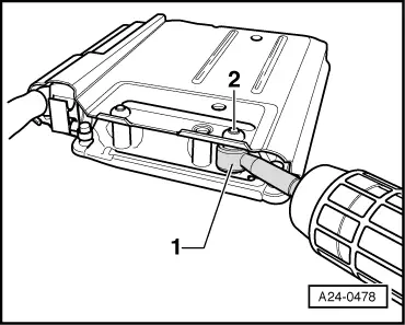
→ To render access to connectors at engine control unit more difficult (anti-theft protection), engine control unit -1- is bolted by way of a catch -2- and shear bolts -3- to a sheet-metal housing -4-. Locking fluid is applied to thread of shear bolts to make bolts more difficult to screw out. Engine control unit must be separated from sheet-metal housing to unplug connectors from engine control unit (e.g. when connecting up test box or replacing engine control unit). This procedure is described in the following. Tools required: |
 |
|
Procedure: Attention:
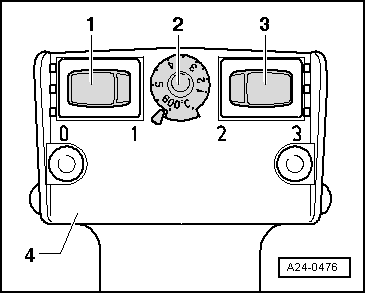
To avoid damaging (scorching) wires, connectors, insulation and control units, always adhere exactly to the following operations and heed operating instructions for hot-air blower. |
|
|
|
 |
|
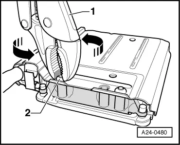
Note: Then use hot-air blower to heat thread of catch, into which shear bolts are screwed. This operation is designed to reduce the inhibiting action of the locking fluid on the shear bolt thread to make it easier to screw out the shear bolts afterwards. Attention:
Warming the thread of the catch also greatly increases the temperature of the shear bolts and sheet-metal housing components. Take care to avoid burns. It is also important to ensure that only the thread is heated and none of the surrounding components if at all possible (these should be covered if necessary). |
 |
|
|
 |
|
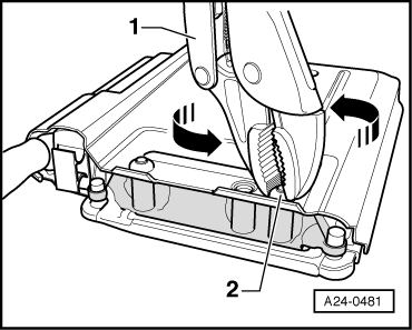
Employ exactly the same procedure for the second shear bolt, taking particular care to avoid the control-unit connectors in the immediate vicinity. |
 |
|
|
 |
|
Engine control unit can now be separated from sheet-metal housing.
Installing Install in reverse order, paying attention to the following: The following steps must be performed after connecting new engine control unit:
Use is to be made for this purpose of vehicle diagnostic, testing and information system VAS 5051. |