
A4 Mk2
 |
|
Note: After switching on ignition, fuel pump runs continuously, even if engine is not running. Reason: Fuel pump relay receives positive supply via central electrics unit after switching on ignition. Earth is applied to fuel pump relay via cable link in test box.
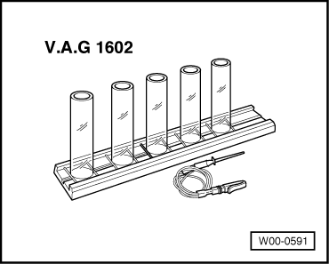
Checking injection quantity
|
 |
|
Specification for each injector: 105 ... 125 ml If reading does not match specification for all injectors:
If reading does not match specification for one injector:
Note: Spray pattern is also to be checked when checking injection quantity. It must be the same for all injectors. Fuel rail with injectors is to be installed appropriately in reverse order of removal paying attention to the following:
|