audi Workshop Repair Guides

Audi Workshop Service and Repair Manuals

Ignition system, glow plug system > < Wiring and component check with test box V.A.G 1598/31
Simos injection and ignition system (4-cyl.)
Servicing Simos injection system
Renewing engine control unit

The following procedure applies to engine control units not fitted with a protective metal casing. Refer to for engine control units with protective metal casing.

Note:

When the engine control unit is disconnected the learned values are erased but the contents of the fault memory remain intact.

Removing engine control unit

 
A87-0314
  • ‒ Connect vehicle diagnostic, testing and information system VAS 5051 with diagnosis lead VAS 5051/1 and select address word "01" for engine electronics control unit. The ignition should be switched on.

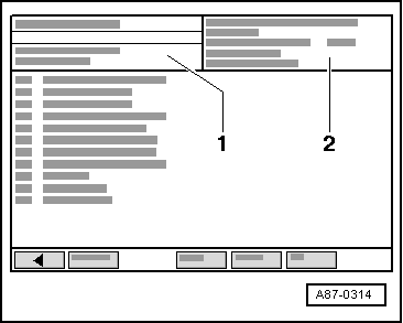
→ The display of fault reader VAS 5051 will show the control unit identification and coding -2-.

  • ‒ Always start by calling up and printing out the control unit identification.
  • ‒ Switch off ignition.
 
A23-0164
  • ‒ → Pull off rubber seal -1- from plenum chamber to the front.
  • ‒ Take off plenum chamber cover.
  • ‒ Remove both windscreen wiper arms -2- (mark positions before removal).
  • ‒ Unclip scuttle panel trim (see arrows).

 
A23-0163
  • ‒ → Remove control unit housing cover.
 
N28-0123
  • ‒ → Carefully lever off the retainer bar with a screwdriver -arrow-.

 
A10-0762
  • ‒ → Release retainer catch -arrows- and unplug connectors -1- and -2- from control unit.
  • ‒ Remove engine control unit and fit a new control unit.

Installing engine control unit

Installation is performed in the reverse sequence.

The following step needsto be performed after connecting the new engine control unit:

  • ‒ Activate the engine control unit via the "Guided fault finding" function (diagnosis object "Renewing engine control unit").

For this step use vehicle diagnostic, testing and information system VAS 5051.

Procedure for replacing an engine control unit with a bolted protective metal casing

Removing

 
A87-0314
  • ‒ Connect the vehicle diagnostic, test and information system VAS 5051 and select the vehicle system "01 - Engine electronics". When doing this the ignition must be on.

→ The display on vehicle diagnostic, test and information system VAS 5051 will show the control unit identification and the coding -2-.

  • ‒ Always start by calling up and printing out the control unit identification.
  • ‒ Switch off ignition.
 
A27-0088
  • ‒ → Remove rubber seal from plenum chamber in direction of arrow-.
  • ‒ Remove plenum chamber cover -1- from the front.

 
A20-0833
  • ‒ → Lever off cover caps -3- (2x) with a screwdriver.
  • ‒ Loosen hexagon nuts -4- several turns.
  • ‒ Disengage wiper arms -2- from their shafts by lifting them gently.
  • ‒ Remove hexagon nuts completely and take off wiper arms.
  • ‒ Pull off securing clips -1- and remove scuttle panel grille -5-.
 
A10-0996

  • ‒ → Remove cover for electronics box in plenum chamber -arrows-.

 
A24-0483
  • ‒ → Carefully lever off the retainer bar with a screwdriver -arrow-.

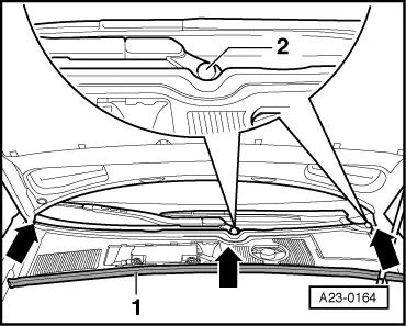
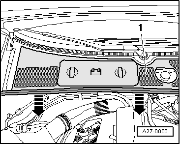
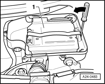
Note:

Item -1- in the illustration shows the engine control unit with protective metal casing.

 
A24-0477

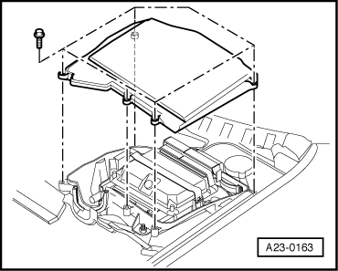
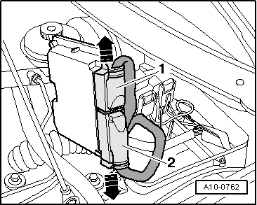
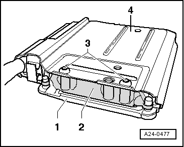
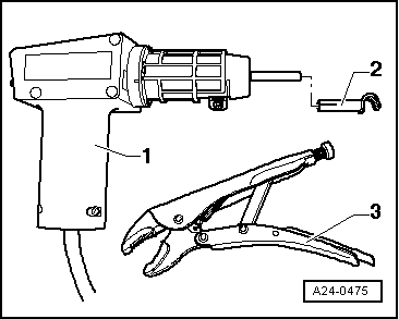
→ As a deterrent against unauthorised access to the connectors on the engine control unit, the control unit -1- is bolted to a metal casing -4- by means of shear bolts -3- and a locking plate -2-.

The threads of the shear bolts are additionally coated with a thread-locking compound to make them more difficult to remove.

In order to unplug the connectors from the engine control unit (for instance when connecting the test box or replacing the control unit), the control unit must be separated from the protective casing. The required procedure is described below:

The following tools are required:

 
A24-0475
  • ◆ → Hot-air blower -1- (from wiring repair set VAS 1978)
  • ◆ Nozzle attachment -2- (also included in wiring repair set VAS 1978)
  • ◆ A normal (commercially available) vice-grip wrench

Procedure:

Caution
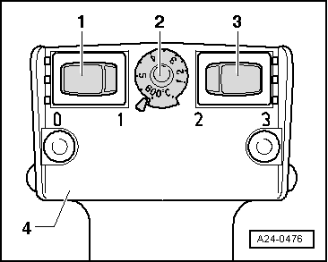
Keep exactly to the following procedure to avoid damage (burning) to the wiring, connectors, insulation or the control units. Follow the operating instructions supplied with the hot-air blower.
 
A24-0477
  • ‒ → Pivot engine control unit with protective casing towards engine compartment so that locking plate (Item -2- in illustration) is visible. Place a clean cloth under engine control unit with protective casing.
 
A24-0476
  • ‒ → Set controls on hot-air blower as shown in illustration:
    temperature control -2- to maximum heat and two-stage air delivery switch -3- to setting 3.

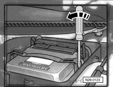
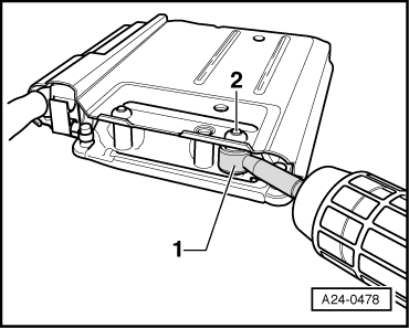
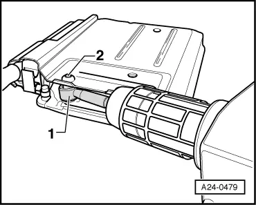
Note:

In the next step the blower is used to heat the threads for the shear bolts in the locking plate. This reduces the effect of the thread-locking compound so the bolts can then be removed more easily.

Warning
When the threads in the locking plate are heated up, this also heats the shear bolts and parts of the metal casing. Take care not to burn your hands. Also make sure that, as far as possible, you only apply heat to the threads and not to the adjacent parts. Cover these up if necessary.

 
A24-0478
  • ‒ → Apply nozzle -1- of hot-air blower to the thread in the locking plate so that the nozzle surrounds the thread. You can let the nozzle rest against the top of the metal casing.
  • ‒ Switch on the blower and apply heat to the thread for about 20 to 25 seconds.

 
A24-0481
  • ‒ → Apply vice-grip wrench -1- to bolt head -2- and unscrew shear bolt in direction indicated (arrows).

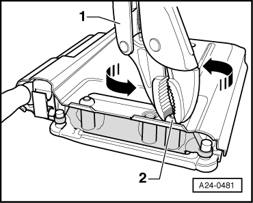
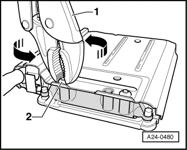
Repeat the procedure for the second shear bolt. Be particularly careful here because the control unit connectors are very close to this bolt.

 
A24-0479
  • ‒ → Apply nozzle -1- of hot-air blower to the second thread in the locking plate so that the nozzle surrounds the thread. You can let the nozzle rest against the top of the metal casing.
  • ‒ Switch on the blower and apply heat to the thread for about 20 to 25 seconds.

 
A24-0480
  • ‒ → Apply vice-grip wrench -1- to bolt head -2- and unscrew shear bolt in direction indicated (arrows).

The engine control unit can now be separated from the metal casing.

  • ‒ Release connectors on engine control unit and unplug connectors.
  • ‒ Take out the old engine control unit and install the new one.

Installing

After competing repair, install metal casing on engine control unit. Use new shear bolts.

Install in reverse sequence; note the following points:

The following step needsto beperformed after connecting the new engine control unit:

  • ‒ Activate the engine control unit via the "Guided fault finding" function (diagnosis object "Renewing engine control unit").

For this step use vehicle diagnostic, testing and information system VAS 5051.

Ignition system, glow plug system > < Wiring and component check with test box V.A.G 1598/31