
A4 Mk2
| Overview of fitting locations |
 Note
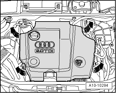
Note| t | Some components are located beneath the engine cover panel. For removal refer to → Fig.. |
| t | Components “A” to “G” for vehicles with particulate filter are not shown in the diagram. |
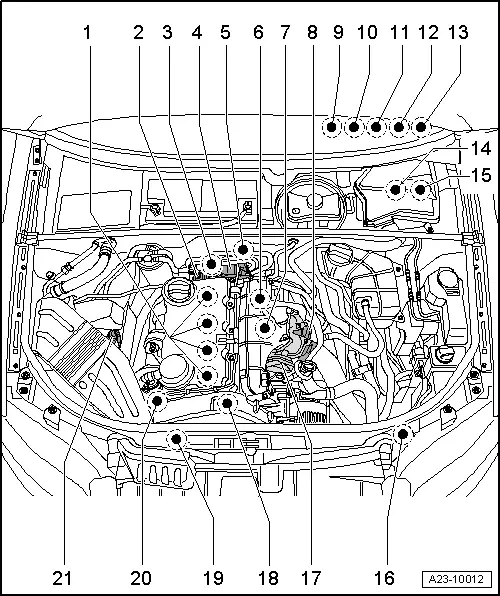
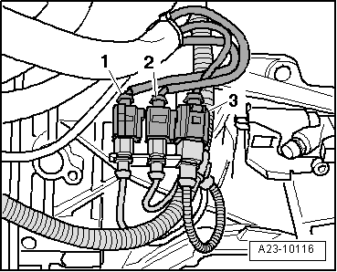
| 1 - | Unit injectors and glow plugs |
| q | Unit injector solenoid valve, No. 1 cyl. -N240- |
| q | Unit injector solenoid valve, No. 2 cyl. -N241- |
| q | Unit injector solenoid valve, No. 3 cyl. -N242- |
| q | Unit injector solenoid valve, No. 4 cyl. -N243- |
| q | Removing and installing unit injectors → Chapter |
| q | Glow plug 1 -Q10- |
| q | Glow plug 2 -Q11- |
| q | Glow plug 3 -Q12- |
| q | Glow plug 4 -Q13- |
| q | Different types of glow plugs → Chapter |
| q | Removing and installing metal glow plugs → Chapter |
| q | Removing and installing ceramic glow plugs → Chapter |
 Caution
|
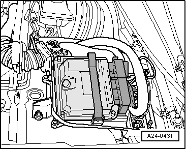
| 2 - | Multi-pin connector |
| q | For unit injectors and glow plugs |
| q | Fitting location → Fig. |
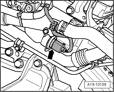
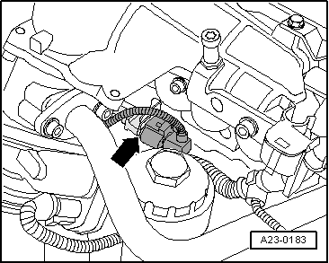
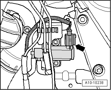
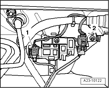
| 3 - | Coolant temperature sender -G62- |
| q | Fitting location → Fig. |
| q | Dissipate cooling system pressure before removal if necessary |
| 4 - | Tandem pump |
| q | Removing, installing and checking → Rep. Gr.20 |
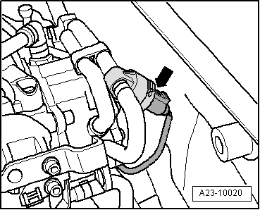
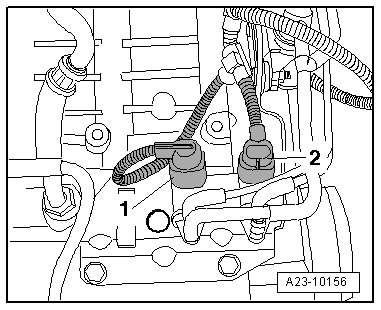
| 5 - | Fuel temperature sender -G81- |
| q | Fitting location → Fig. |
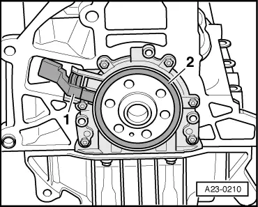
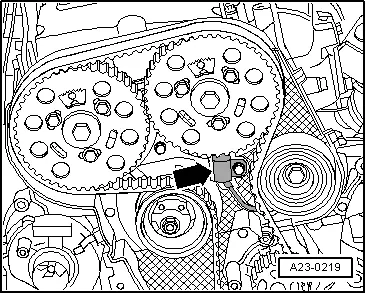
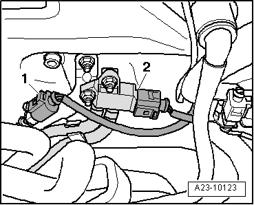
| 6 - | Engine speed sender -G28- |
| q | Fitting location → Fig. |
| 7 - | 3-pin connector |
| q | For Hall sender -G40- |
| q | Fitting location → Fig. |
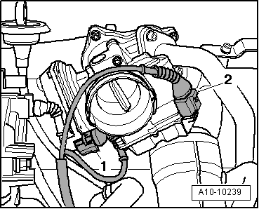
| 8 - | Intake manifold flap motor -V157- |
| q | Fitting location → Fig. |
| 9 - | Exhaust emissions warning lamp -K83- |
| q | In instrument cluster |
| 10 - | Accelerator position sender -G79- with accelerator position sender 2 -G185- |
| q | Fitting location → Fig. |
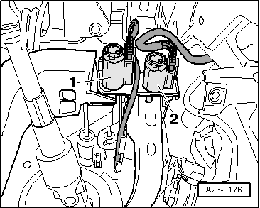
| 11 - | Brake light switch -F- and brake pedal switch -F47- |
| q | Fitting location → Fig. |
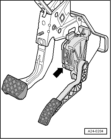
| 12 - | Clutch pedal switch -F36- |
| q | Fitting location → Fig. |
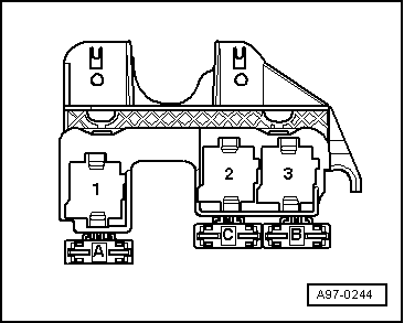
| 13 - | 3-position relay and fuse holder behind dash panel (left-side) |
| q | With low heat output relay -J359- |
| q | With high heat output relay -J360- |
| q | Fitting location → Fig. |
| q | Not installed on vehicles with auxiliary heater. |
| 14 - | Engine control unit -J623- |
| q | Fitting location → Fig. |
| q | Removing and installing → Chapter |
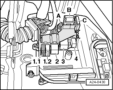
| 15 - | Relay and fuse holder in electronics box in plenum chamber (left-side) |
| q | With fuel pump relay -J17- |
| q | With terminal 30 voltage supply relay -J317- |
| q | With automatic glow period control unit -J179- |
| q | With engine glow plug strip fuse -S39- |
| q | Fitting location → Fig. |
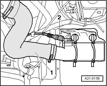
| 16 - | Charge air pressure sender -G31- with intake air temperature sender -G42- |
| q | Fitting location → Fig. |
| 17 - | Exhaust gas recirculation valve -N18-/exhaust gas recirculation potentiometer -G212- |
| q | Fitting location → Fig. |
| 18 - | Hall sender -G40- |
| q | For camshaft position |
| q | Fitting location → Fig. |
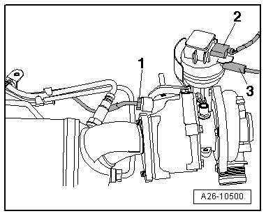
| 19 - | Solenoid valve for charge pressure control -N75- |
| q | Fitting location → Fig. |
| 20 - | Exhaust gas recirculation cooler change-over valve -N345- and intake manifold flap valve -N316- |
| q | Intake manifold flap valve -N316- (only for engine code letters BRD, BVA) |
| q | Fitting location → Fig. |
| 21 - | Air mass meter -G70- |
| A - | Lambda probe -G39- with Lambda probe heater -Z19- and temperature sender before particulate filter -G506- |
| q | Fitting location → Fig. |
| q | Removing and installing Lambda probe -G39- with Lambda probe heater -Z19- → Chapter |
| q | Removing and installing temperature sender before particulate filter -G506- → Rep. Gr.26 |
| B - | Temperature sender after particulate filter -G527- |
| q | Fitting location → Fig. |
| q | Removing and installing → Rep. Gr.26 |
| C - | Exhaust gas temperature sender 1 -G235- |
| q | Fitting location → Fig. |
| q | Removing and installing → Rep. Gr.26 |
| D - | Electrical connectors on left side of bulkhead |
| q | For exhaust gas temperature sender 1 -G235- |
| q | For Lambda probe -G39- |
| q | Fitting location → Fig. |
| E - | Electrical connectors on right side of bulkhead and exhaust gas pressure sensor 1 -G450- |
| q | For exhaust gas pressure sensor 1 -G450- |
| q | For temperature sender before particulate filter -G506- |
| q | Fitting location → Fig. |
| F - | Electrical connections on gearbox (left-side) |
| q | For temperature sender after particulate filter -G527- |
| q | Fitting location → Fig. |
| G - | Position sender for charge pressure positioner -G581- |
| q | Depending on version |
| q | Fitting location → Fig. |
|
|
|
|
|
|
Note
|
|
|
|
|
|
|
|
|
|
|
|
|
|
|
|
|
|
|
|
Note
|
|
Note
|
|
|
|
|
|
|
|
|
|
|
|
Note
|
|
Note
|
|