audi Workshop Repair Guides

Audi Workshop Service and Repair Manuals

Removing and installing intake manifold flap motorV157 or intake manifold flap 2 motorV275 > < Removing and installing bottom section of intake manifold (left-side)
Removing and installing bottom section of intake manifold (right-side)
   
Removing and installing bottom section of intake manifold (right-side)
Special tools and workshop equipment required
t  Torque wrench -V.A.G 1331-
t  Ratchet -V.A.G 1331/1-
t  Tool insert, AF 19 -V.A.G 1331/5- for vehicles from 09.2005 onwards
t  Socket -T40055-, 17 mm for vehicles from 09.2005 onwards

   
t  Socket insert AF 14, flared ring spanner -V.A.G 1331/8- for vehicles up to 09.2005
  W00-10342
t  Socket, 14 mm -3150- for vehicles up to 09.2005
Removing
  Caution
t  Always read rules for cleanliness and instructions for working on fuel system → Chapter.
t  Follow these instructions and rules for cleanliness before starting work and while working on the fuel system.
–  Remove engine cover panel → Chapter.
Vehicles up to 09.2005:
  W00-0282
–  Unscrew union nuts -arrows- and detach high-pressure pipes.
Vehicles from 09.2005 onwards:
  A15-10023
–  Unscrew union nuts -1 ... 4- and detach high-pressure pipes.
All vehicles:
–  Remove intake manifold (top section) → Chapter.
–  Pull crankcase breather hose off air pipe -arrow-.
  A23-10128
–  Remove bolts -2- and -3-.
–  Release hose clip -1- and detach air pipe at air mass meter -G70- and at turbocharger.
  A21-10028
–  Take electrical connector -arrow- for exhaust gas temperature sender 1 -G235- out of bracket.
  A23-10055
–  Detach electrical connector -3- at intake manifold flap motor -V157-.
–  Remove bolt -2-.
  Note
Disregard items -1- and -4-.
–  Detach electrical connectors at glow plugs on cylinder bank (right-side).
  A19-10047
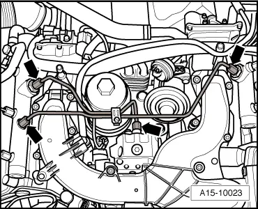
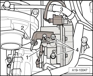
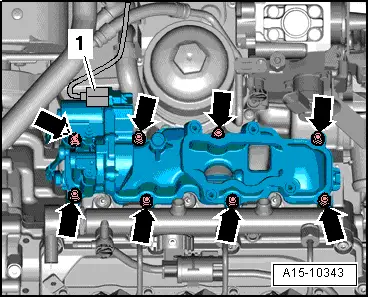
–  Remove bolts -arrows- and detach bottom section of intake manifold (right-side).
  Note
t  Disregard -item 1-.
t  Block off intake ports in cylinder head with clean rags.
Installing
Installation is carried out in the reverse order; note the following:
  Note
Renew seals and gaskets.
–  Install intake manifold (top section) → Chapter.
  Note
t  
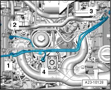
Note identification marks for cylinder allocation when re-installing high-pressure pipes.
t  The high-pressure pipes can be re-used after performing the following checks:
t  Check taper seats of high-pressure pipes for deformation and cracks.
t  The bore of the pipe must not be distorted, restricted or otherwise damaged.
t  Corroded pipes must not be used again.
–  Lubricate threads of union nuts with fuel.
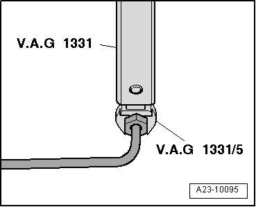
–  Tighten union nuts on high-pressure pipes hand-tight initially.
–  Ensure that high-pressure pipes are not under tension.
  A15-10343
Vehicles up to 09.2005:
–  To tighten union of high-pressure pipe at high-pressure pump, use torque wrench -V.A.G 1331- with socket insert AF 14, flared ring spanner -V.A.G 1331/8-.
  A13-10043
–  To tighten unions of high-pressure pipes at rail elements, use torque wrench -V.A.G 1331- with ratchet -V.A.G 1331/1- and socket, 14 mm -3150-.
  A23-0225
Vehicles from 09.2005 onwards:
–  To tighten union of high-pressure pipe at high-pressure pump, use torque wrench -V.A.G 1331- with ratchet -V.A.G 1331/1- and socket -T40055-, 17 mm.
  A13-10038
–  To tighten unions of high-pressure pipes at rail elements, use torque wrench -V.A.G 1331- with tool insert, AF 19 -V.A.G 1331/5-.
All vehicles:
–  Check fuel system for leaks → Chapter.
Tightening torques
  A23-10095
ComponentNm
Intake manifold (bottom section) to cylinder head9
High-pressure pipes25


Removing and installing intake manifold flap motorV157 or intake manifold flap 2 motorV275 > < Removing and installing bottom section of intake manifold (left-side)