| –
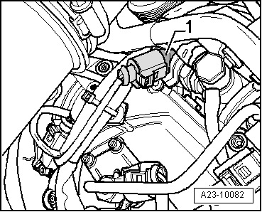
| Detach electrical connector -1- on fuel pressure regulating valve -N276-. |
| –
| Slacken union nut (counterhold at hexagon flats on housing). Then unscrew and remove by hand. |
| –
| Extract dirt from opening in rail (threads and sealing surface). Do not use metal tools, etc. |

Note | Seal off opening in rail immediately with a suitable plug to prevent dirt from entering. |
Note | t
| The fuel pressure regulating valve -N276- has a deformable sealing lip and no separate seal; it can therefore be used only once. |
| t
| Check that sealing surfaces (deformable sealing lip) and threads on new fuel pressure regulating valve -N276- are not damaged. |
| t
| Check sealing surface at opening in rail. |
| t
| Thread on fuel pressure regulating valve -N276- must be free of oil and grease. |
| –
| Screw on union nut by hand. |
| –
| Align regulating valve so that connecting wire is free of tension after connector is attached. |
| –
| Hold regulating valve in this position with pliers (water pump pliers or similar). |
| –
| Use suitable torque wrench with suitable open-end spanner insert to tighten union nut. |
Note | t
| There are different tightening torques for vehicles manufactured »before« November 2005 and for vehicles manufactured »after« November 2005. |
| t
| To find out whether the vehicle was manufactured before or after November 2005: unplug electrical connector from throttle valve module -J338- and count the pins. |
| t
| 4 pins = manufactured before November 2005 |
| t
| 5 pins = manufactured after November 2005 |
| Tightening torques for vehicles manufactured before November 2005 |
| Tighten union nut in 2 stages. |
| Stage 1: 60 +/-5 Nm (counterhold hexagon flats on housing). |
| Then back off union nut 90° (1/4 turn; counterhold hexagon flats on housing). |
| Stage 2: 80 +5 Nm (counterhold hexagon flats on housing). |
| Tightening torques for vehicles manufactured after November 2005 |
| Tighten union nut in 2 stages. |
| Stage 1: 60 +/-5 Nm (counterhold hexagon flats on housing). |
| Then back off union nut 90° (1/4 turn; counterhold hexagon flats on housing). |
| Stage 2: 95 +5 Nm (counterhold hexagon flats on housing). |
| –
| Tighten banjo bolt for fuel return lines with new seals to 25 Nm. |
| –
| The remaining installation steps are carried out in the reverse sequence. |
| –
| After installation, run engine at moderate speed for several minutes and then switch off. |
| –
| Check fuel system for leaks. |
| –
| Interrogate fault memory. |
| –
| After completing the repair, road-test the vehicle. Accelerate with full throttle at least once. Then check the high-pressure section of the fuel system again for leaks. |
| –
| Interrogate fault memory again. |
|
|
|
 WARNING