
A4 Mk2
| Dismantling and assembling triple roller joint AAR 2900 |
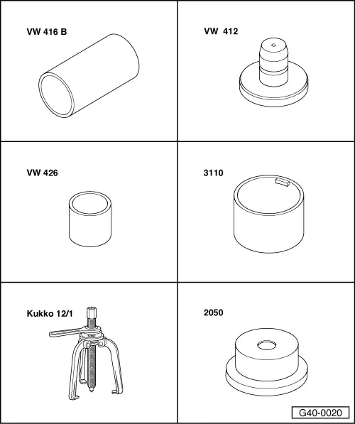
| Special tools and workshop equipment required |
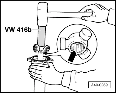
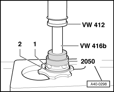
| t | Tube -VW 416 B- |
| t | Press tool -VW 412- |
| t | Tube -VW 426- |
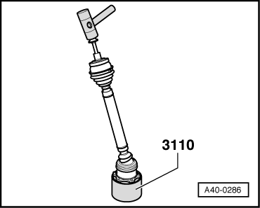
| t | Tube -3110- |
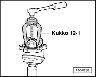
| t | Puller -Kukko 12/1- |
| t | Thrust piece -2050- |

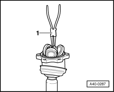
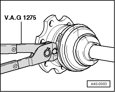
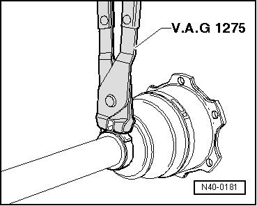
| t | Pliers -V.A.G 1275- |
| t | Circlip pliers -VW 161 A- |
| t | Spindle -3207- |
 Note
Note
|
|
|
|

|
|
|
|
|
|
|
Note
|
|
|
|
Note
|
|
Note
|
|
Note
|
|
|
|
|
|