
A4 Mk2
|
|
|
|
|
| Exploded view |
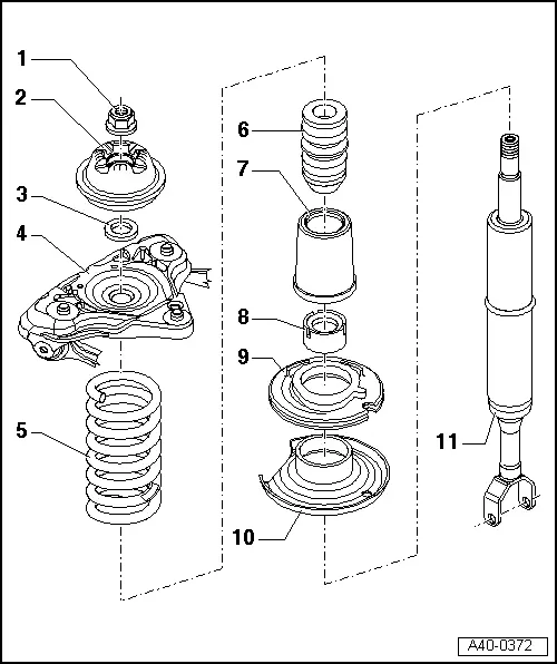
| 1 - | Flange nut |
| q | 50 Nm |
| q | Always renew |
| 2 - | Shock absorber mounting |
| 3 - | Washer |
| 4 - | Mounting bracket |
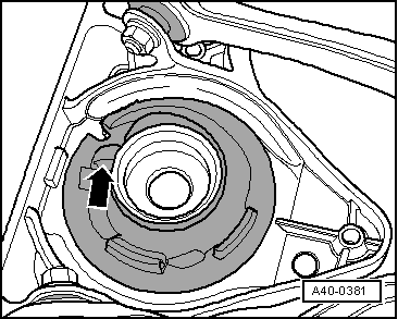
| q | Installation position → Anchor |
| 5 - | Coil spring |
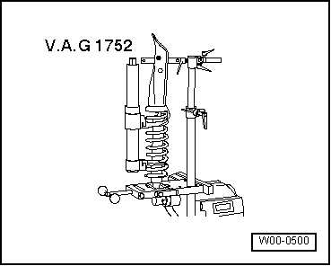
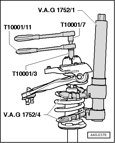
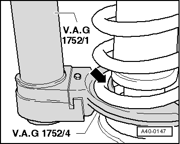
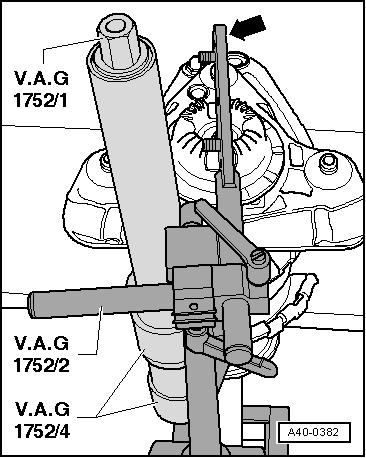
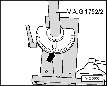
| q | Removing → Fig. and → Fig. |
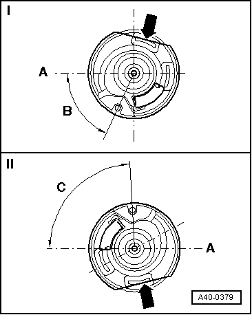
| q | Installing → Fig. |
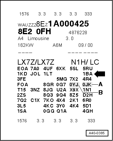
| q | Note different running gear versions; see vehicle data sticker → Anchor |
| q | For correct version refer to → Parts catalogue |
| 6 - | Auxiliary spring |
| 7 - | Protective sleeve |
| 8 - | Protective cap |
| 9 - | Bottom spring seat |
| 10 - | Bottom spring plate |
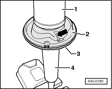
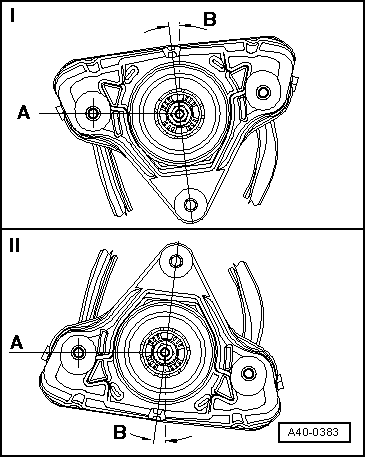
| q | Installation position → Fig. |
| 11 - | Shock absorber |
| q | Renewing → Fig. |
| q | Note different running gear versions; see vehicle data sticker → Anchor |
| q | Defective shock absorbers must always be degassed and drained before disposal → Chapter |
| q | For correct version refer to → Parts catalogue |
|
|
|
|
|
|
|
|
|
|
|
|
|
|
|
|
|
|
|
|
|
|
|
|
|
|
|