
A4 Mk2
| Operating electronics control unit for navigation -J402- |
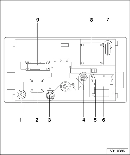
| 1 - | Connection HF (black) from navigation interface -R94- |
| 2 - | Fan |
| 3 - | Connection ZF (intermediate frequency) (yellow) to aerial selection control unit -J515- / left aerial module -R108- |
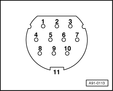
| 4 - | Multi-pin connector, 11-pin (T11) from navigation/TV tuner -J415- |
| 5 - | Earth connection |
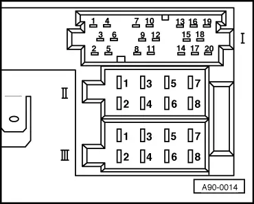
| 6 - | Connection block with three multi-pin connectors and one fuse for unit |
| 7 - | GPS connection (blue) from navigation aerial -R50- |
| 8 - | Fan |
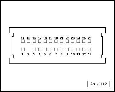
| 9 - | Multi-pin connector, 26-pin, black (T26) |
 Note
Note
|
|
|
|
|
|
|
|
|
|
|