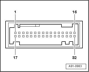
| 1 - Multi-pin connector, 32-pin, black (T32f) |
| 13 - | Audio input (right-side) from navigation/TV tuner -J415- |
| 15 - | Video input sync. from navigation/TV tuner -J415- |
| 16 - | Video input (green) from navigation/TV tuner -J415- |
| 27 - | Screen earth from navigation/TV tuner -J415- |
| 28 - | Audio earth from navigation/TV tuner -J415- |
| 29 - | Audio input (left-side) from navigation/TV tuner -J415- |
| 30 - | Video earth from navigation/TV tuner -J415- |
| 31 - | Video input (blue) from navigation/TV tuner -J415- |
| 32 - | Video input (red) from navigation/TV tuner -J415- |
|
|
|

 Note
Note