
A4 Mk3
| Exploded view - tank flap |
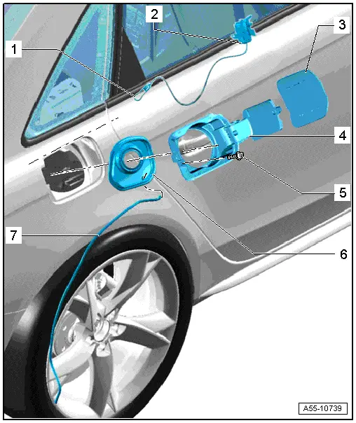
| 1 - | Cable for manual release |
| 2 - | Tank filler flap locking motor -V 155- |
| q | Removing: |
| – | Tank flap removed |
| – | Detach cable from convenience system central control unit -J393- in luggage compartment and pull through towards the front. |
| – | Detach tank filler flap locking motor -V 155- from body flange towards the front and unplug electrical connector. |
| q | Installing: |
| – | Push tank filler flap locking motor -V 155- onto flange and at the same time push manual release through into luggage compartment. |
| 3 - | Lid for tank flap |
| q | Removing → Fig. |
| 4 - | Tank flap |
| q | Must be renewed following removal. |
| – | Remove lid for tank flap → Fig.. |
| – | Guide cable through opening in tank flap cup. |
| – | Insert tank flap at an angle until retaining tabs engage at flange in side panel. |
| – | Bolt together tank flap and tank filler flap locking motor with bolt -4-. |
| 5 - | Bolt |
| q | 1.7 Nm |
| 6 - | Tank flap unit |
| 7 - | Drain hose |
| q | Route without kinking |
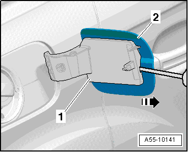
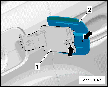
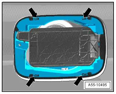
| Renewing tank flap unit |
| 1 - | Tank flap cup |
| 2 - | Tank filler flap locking motor -V 155- |
| 3 - | Bolt |
| q | 1.7 Nm |
| 4 - | Tank flap unit |
| – | Removing → Anchor |
|
|
|
|
|
|
|
|
|
|
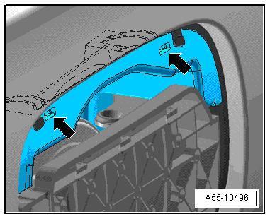
| Manual release for tank flap |
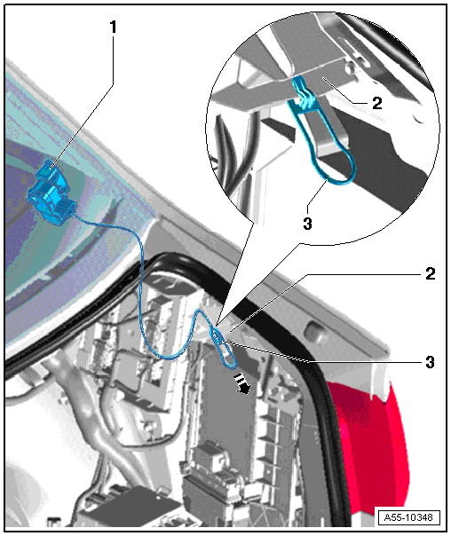
| 1 - | Tank filler flap locking motor -V 155- |
| 2 - | Cable for manual release |
| q | Insert tank filler flap locking motor -V 155- with cable through tank flap opening, as shown. |
| q | Pull cable through towards rear into interior and fit with lug on flange on convenience system central control unit -J393-. |
| 3 - | Side panel |
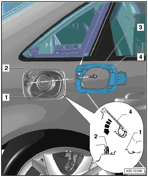
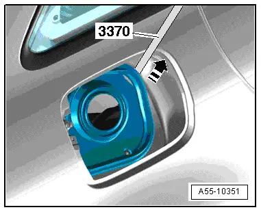
| Installation position of tank flap |
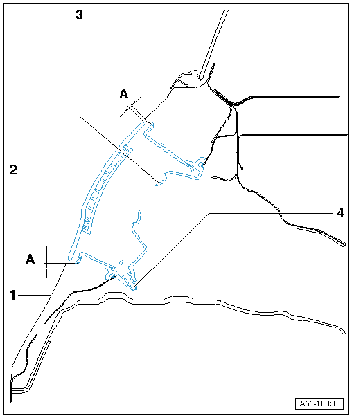
| 1 - | Side panel |
| 2 - | Lid for tank flap |
| q | Adjust distance -A- = 2.2 mm (even distance from side panel). |
| 3 - | Tank flap cup |
| q | Fit onto body flange all around (as shown). |
| 4 - | Drain hose |
| q | Route without kinking |
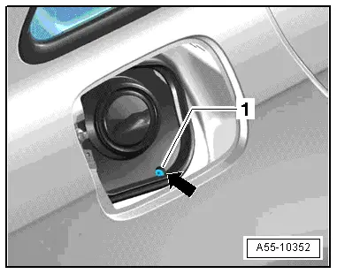
| Drain hose for tank flap |
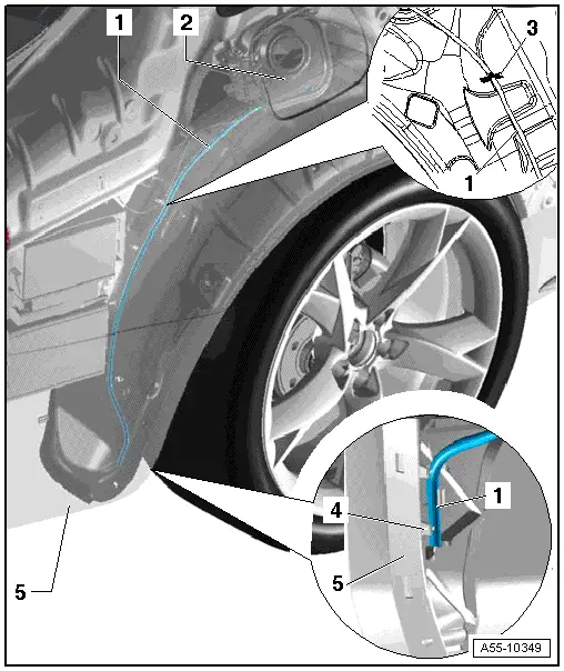
| 1 - | Drain hose |
| – | Route drain hose under wheel housing liner, as shown, and insert into guide. |
| 2 - | Tank flap |
| 3 - | Wheel housing liner |
| q | Loosen in area of drain hose and push to side. |
| 4 - | Bumper (rear) |
| 5 - | Guide (rear) |
| q | Drain hose inserted into guide (bottom), as shown. |