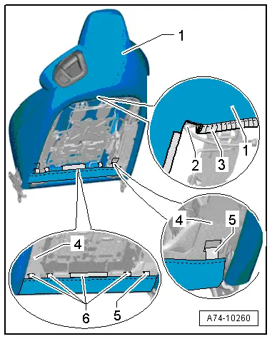
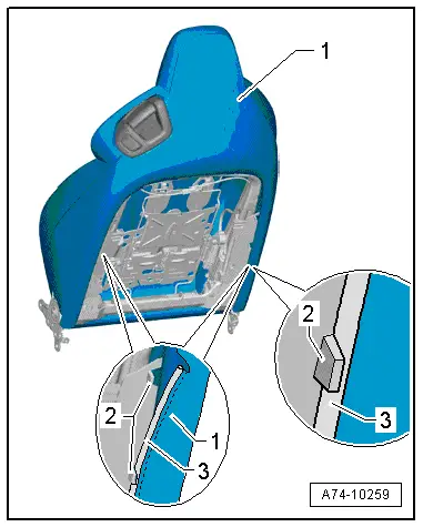
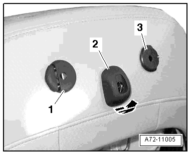
| Vehicles with mounting for DVD player: |
| l
| Mountings for guides -1- and -3- on backrest must be clean. |
| –
| Align backrest cover and insert guides in mountings. |
| l
| Guides -1- and -3- can only be inserted in one position. |
| l
| Release buttons must face outwards. |
| l
| Trim can only be clipped on in one position. |

Note | -Arrow- can be disregarded. |
| All vehicles (continued): |
Note | Make sure electrical connectors are fitted correctly (as far as stop) and engage audibly. |

WARNING | The battery must be connected with the ignition switched on. If pyrotechnic components (e.g. airbag or belt tensioner) are inexpertly repaired, this may result in unwanted triggering after connecting the battery. There must not be anyone in the vehicle while you are connecting the battery. |
|
Note | If the airbag warning lamp -K75- indicates a fault following installation, you must interrogate, erase and then re-interrogate the event memory → Vehicle diagnostic tester. |
|
|
|
 Caution