| t
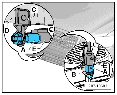
| This illustration shows the position of the ambient temperature sensor -G17--A- on an Audi A5 Coupé. The layout may be different on an Audi A5 Sportback, Audi A4, Audi Q5 etc. |
| t
| On vehicles on which -G17--A- is fitted with the holder -B- at the air inlet grille above the carrier, an excessively high temperature may be measured under certain usage conditions on account of the fitting location of -G17- (due to the radiant heat of the radiator and the condenser, e.g. on Model Year 2008 vehicles). The fitting location of -G17--A- is therefore gradually being altered in Model Year 2009. -G17- is to be fitted with a modified holder -C- slightly further forwards (closer to the radiator grille) and beneath the carrier -D- → Electronic parts catalogue. |
| t
| In the event of problems with an excessively high measured value on vehicles on which -G17--A- is fitted with the holder -B- at the air inlet grille above the carrier, install -G17--A- with a modified holder -C- slightly further forwards (closer to the radiator grille) and beneath the carrier -D-. Depending on the version, it may also be necessary to lengthen the wiring → Electronic parts catalogue. The holder -C- is clipped in at the carrier -D- (if not already provided, a hole with a diameter of 7 mm must be made at the bottom of the carrier -D-). |
| –
| Switch off the ignition. |
| –
| Unplug the connector -E- at the temperature sensor -A- and unclip the temperature sensor from the holder (-B- or -D-). |

Note | Depending on the vehicle equipment, it may be necessary to detach the bumper in order to remove -G17--A- from the holder -C- installed beneath the carrier -D- (if -G17- is not accessible from above on vehicles with additional radiators for example). |
|
|
|
