| –
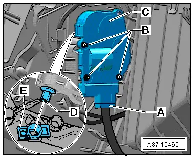
| Mark the connector -A- (to prevent interchange if several connectors are simultaneously unplugged). |
| –
| Unplug the connector -A-. |
| –
| Detach the shaft -D- of the control motor -C- from the shaft of the centre vent flap -E-. |
| Install in reverse order; paying attention to the following: |
| –
| Insert the shaft -D- of the control motor -C- in the shaft of the centre vent flap -E-. |

Note | The control motor has no stop. The shaft of the control motor can thus be inserted in any position in the shaft of the centre vent flap -E-. |
| –
| Plug in the connector -A-. |
| –
| Lay the wiring harness such that it cannot come into contact with moving components (e.g. lever). |
| –
| Re-install all the other parts removed in reverse order. |
| –
| Switch on the ignition. |
Note | t
| During basic setting, control motor assignment and adaption are implemented on the basis of the arrangement in the series connection of the wiring. If the sequence is not as specified, the matching of the control motors and thus flap control will not be correct → Chapter (block diagram of air conditioner control motors). |
|
|
|