| –
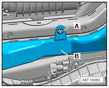
| To prevent interchange, mark the connector -A- (to the right centre vent control motor -V111-) and -B- (right footwell flap control motor -V109-). |
| –
| Unplug the connectors -A- and -B-. |
| –
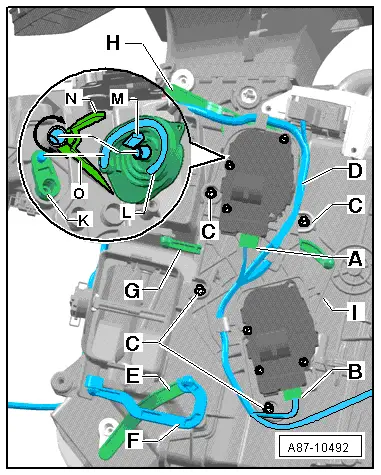
| Unplug the connector from the evaporator output temperature sender -G263- → Chapter. |
| –
| Unfasten the wiring -D- from the attachment points at the mounting plate -J-. |
| –
| Carefully unfasten the various connecting rods (from -E- to -H-) from the levers at the corresponding flaps. |

Note | t
| The connecting rods (from -E- to -H-) are clipped in at the levers. Unclip carefully to avoid damaging the lever. |
| –
| Detach the mounting plate -J- (with the control motors and levers, cam plates and connecting rods) from the air conditioning unit. |
| Install in reverse order; paying attention to the following: |
| –
| Moisten the guides of the cam plate as well as the pins at the flap levers with a small quantity of grease (e.g. lubricating paste -G 000 150- → Electronic parts catalogue). |
| –
| Check for proper assembly of the levers, cam plates and connecting rods of the mounting plate -J- → Chapter. |
| –
| When installing the mounting plate -J-, pay attention to the pins of the lever -K- and the guide of the cam plate -L-. |
Note | When fitting, make sure the stop of the cam plate -M- is inserted between the two stops at the air conditioning unit -N- and -O- (the cam plate must be able to move over the area marked by the arrow). |
| –
| Plug in the connectors -A- and -B- in line with the markings. |
| –
| Secure the wiring harness -D- in the attachment points at the mounting plate -J-. |
| –
| Lay the wiring harness -D- such that it cannot come into contact with moving components (e.g. lever). |
| –
| Re-install all the other parts removed in reverse order. |
Note | t
| During basic setting, control motor assignment and adaption are implemented on the basis of the arrangement in the series connection of the wiring. If the sequence is not as specified, the matching of the control motors and thus flap control will not be correct → Chapter (block diagram of air conditioner control motors). |
| –
| Switch on the ignition. |
| –
| By making different settings on the air conditioner operating and display unit, Climatronic control unit -J255-, direct the air to the various vents and check whether the flow of air out of the vent actually changes in line with the setting. |
|
|
|