audi Workshop Repair Guides

Audi Workshop Service and Repair Manuals

Checking electric supplementary heater > < Removing and installing right heater housing together with right mounting plate for control motors
Removing and installing supplementary air heater elementZ35 / honeycomb element
Removing and installing supplementary air heater element -Z35- / honeycomb element
  Note
t  Vehicles with a diesel engine and vehicles with certain petrol engines (e.g. petrol engines designed for operation with bioethanol „Flex Fuel Vehicle“ as of Model Year 2010 and vehicles with a high-voltage system) are currently fitted with an electric supplementary heater as supplementary air heater → Audi Sales Range. Heat energy is supplied to the air after leaving the heat exchanger of the air conditioning unit in the event of a request from the air conditioner operating and display unit, Climatronic control unit -J255-.
t  The electric supplementary heater (supplementary air heater element -Z35-) is actuated on vehicles with a diesel engine by way of the corresponding engine control unit (the control units exchange the appropriate information by way of the data bus) → "Guided fault-finding" function of vehicle diagnostic, testing and information system VAS 5051 and → Current flow diagrams, Electrical fault finding and Fitting locations.
t  On vehicles with a petrol engine, the electric supplementary heating (supplementary air heater element -Z35-) is actuated by a signal from the operating and display unit, Climatronic control unit -J255- by way of the local data bus (via the same output by which the fresh air blower control unit -J126- is actuated) to the supplementary air heater control unit -J604-. -J604- then actuates the low heat output relay -J359- and the high heat output relay -J360- (and these supply power to -Z35-) → "Guided fault-finding" function of vehicle diagnostic, testing and information system VAS 5051 and → Current flow diagrams, Electrical fault finding and Fitting locations.
t  Checking operation of supplementary air heater element -Z35- → Chapter.
t  On vehicles not fitted with a supplementary air heater element -Z35-, a honeycomb element is installed as spacer element in the air conditioning unit → Chapter (air intake, air outlet and air routing in air conditioning unit) and → Electronic parts catalogue.
t  In Model Year 2009, a modified version of the supplementary air heater element -Z35- (slightly slimmer heating element design) was gradually introduced. Pay attention the correct version and assignment → Electronic parts catalogue.
Removing
–  Switch on the ignition.
–  Set the air outflow direction on the air conditioner operating and display unit, Climatronic control unit -J255- to „DEF“ (to windscreen).
–  Move the front passenger's seat to the rearmost position.
–  Switch off the ignition.
–  Remove the air intake box → Chapter.
–  Unplug the connector from the evaporator output temperature sender -G263- → Chapter.
   
–  Carefully fold back the floor covering in the area of the centre console and detach the earth connection to the supplementary air heater element -Z35--A- from the earth point at the transmission tunnel on the right → Current flow diagrams, Electrical fault finding and Fitting locations.
  Caution
When folding back the floor covering, pay attention to the centre console so as to avoid damage.
–  Unplug the connector -B- and unplug the connector -C- from the right heater housing.
–  Unfasten the wiring to the supplementary air heater element -Z35--D- from the mounts at the right heater housing.
–  Remove the right heater housing → Chapter.
  A87-10521
–  Pull the supplementary air heater element -Z35--A- out of the air conditioning unit.
Installing
Install in reverse order, paying attention to the following:
  A87-10522
–  The supplementary air heater element -Z35- (honeycomb element) installed is to be fitted with the foam seals -A- and -B- supplied in line with the air conditioner version.
1 - Honeycomb element for vehicle with air conditioner of „Basic“ type
2 -  Honeycomb element for vehicle with air conditioner of „Deluxe“ type
3 - Supplementary air heater element -Z35- for vehicle with air conditioner of „Basic“ type
4 - Supplementary air heater element -Z35- for vehicle with air conditioner of „Deluxe“ type
  Note
t  Different temperature settings are possible on vehicles with an air conditioner of the „Deluxe“ type for the left and right side and the rear area. The seal -B- separates the air ducts in the air conditioning unit for the left and right side → Chapter „Air intake, air outlet and air routing in air conditioning unit“.
t  The seal -B- must be bonded centrally onto the honeycomb element of the supplementary air heater element -Z35-.
t  The seal may curl up on insertion if not correctly bonded on.
t  If the seal is damaged or has not been properly installed, cold air can flow past the supplementary air heater element -Z35- (honeycomb element). Proper separation between the left and right side may not be possible on vehicles with an air conditioner of the „Deluxe“ type.
  A87-10523
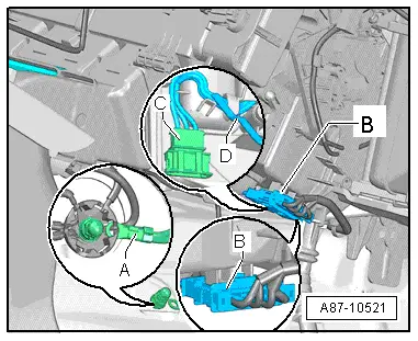
–  Check for contamination of the air conditioning unit, the heat exchanger and the evaporator -B- with the supplementary air heater element -Z35- (honeycomb element) removed and clean off any dirt.
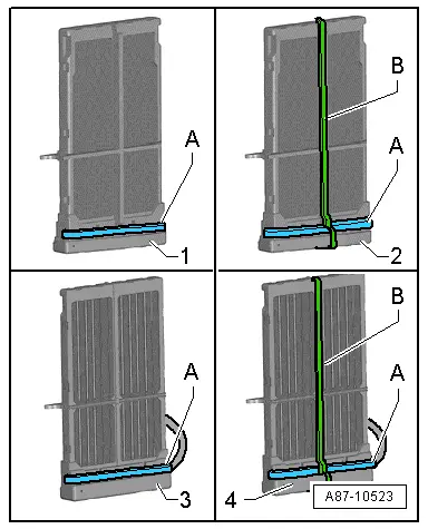
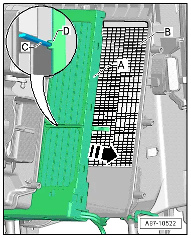
–  Slide the supplementary air heater element -Z35- (honeycomb element) -A- into the air conditioning unit.
  Note
With air conditioners of the „Deluxe“ type, pay attention to the tongue and groove joint -C- and -D- on insertion.
–  Re-install all the components removed in reverse order.
–  Perform air conditioner basic setting and final control diagnosis → "Guided fault-finding" function of vehicle diagnostic, testing and information system VAS 5051.
  Note
t  The control motors on this vehicle are equipped with electronics. A new control motor only learns its position at the air conditioning unit in the course of basic setting and can then be actuated by the air conditioner operating and display unit, Climatronic control unit -J255- (all control motors are identical at present) → "Guided fault-finding" function of vehicle diagnostic, testing and information system VAS 5051.
t  During basic setting, control motor assignment and adaption are implemented on the basis of the arrangement in the series connection of the wiring. If the sequence is not as specified, the matching of the control motors and thus flap control will not be correct → Chapter „Block diagram of air conditioner control motors“.
–  Switch on the ignition.
–  Interrogate the event recorder of the air conditioner operating and display unit, Climatronic control unit -J255- and erase any faults displayed → "Guided fault-finding" function of vehicle diagnostic, testing and information system VAS 5051.
–  Following installation, check actuation and operation of the supplementary air heater element -Z35- if applicable → Chapter.
–  By making different settings on the air conditioner operating and display unit, Climatronic control unit -J255-, direct the air to the various vents and check whether the flow of air out of the vent actually changes in line with the setting.
  A87-10522

Checking electric supplementary heater > < Removing and installing right heater housing together with right mounting plate for control motors