audi Workshop Repair Guides

Audi Workshop Service and Repair Manuals

Removing and installing fresh air blower control unitJ126 > < Removing and installing air recirculation flap control motorV113
Removing and installing temperature flap control motor V68 / rear temperature flap control motor V137
Removing and installing temperature flap control motor -V68- / rear temperature flap control motor -V137-
The temperature flap control motor -V68- is fitted with an air conditioner of the „Basic“ type.
The rear temperature flap control motor -V137- is fitted with an air conditioner of the „Deluxe“ type.
  Note
t  There are different designations and functions depending on the air conditioner version → Chapter (air routing in air conditioning unit and vehicle).
t  On vehicles with an air conditioner of the „Deluxe“ type, the rear temperature flap control motor -V137- actuates the temperature flaps for the rear footwell vents and the vent in the rear centre console (not fitted with air conditioner of „Basic“ type).
t  On vehicles with an air conditioner of the „Basic“ type, the temperature flap control motor -V68- actuates the temperature flaps for the left and right side.
t  At present all the control motors on this vehicle are identical. During basic setting, control motor assignment and adaption are implemented on the basis of the arrangement in the series connection of the wiring. If the sequence is not as specified, the matching of the control motors and thus flap control will not be correct → Chapter (block diagram of air conditioner control motors).
t  Different versions of the levers and connecting elements are fitted at the air conditioning unit depending on the production period → Chapter and → Electronic parts catalogue.
Removing
–  Move the driver's seat to the rearmost position.
–  Switch off the ignition.
–  Remove the storage compartment beneath the dash panel on the driver side → General body repairs, interior; Rep. gr.70.
  Note
The control motor is fitted on the left of the air conditioning unit in the area of the transmission tunnel → Chapter.
   
–  Remove the bolts -B-.
–  Pull the control motor with the corresponding holder -H- in arrow direction -arrow- out of the mounts -C- and -D-.
–  If necessary mark the connector -A- (to prevent interchange with other connectors if several connectors are simultaneously unplugged).
–  Unplug the connector -A-.
–  Unfasten the connecting rod -E- from the toothed segment -F-.
–  Remove the control motor with the corresponding holder.
–  Remove the bolts -G- and separate the control motor from the holder -H-.
  A87-10446
–  Unfasten the toothed segment -A- from the shaft of the control motor -B-.
Installing
Install in reverse order; paying attention to the following:
–  Install the control motor -B- in the holder -D-.
  A87-10447
–  Fit the bolts -G-.
  A87-10446
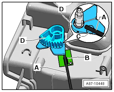
–  Attach the toothed segment -A- as shown to the shaft of the control motor -B-.
  Note
The control motor has no stop. The toothed segment -A- can thus be attached in any position to the shaft of the control motor. To ensure proper operation, the toothed segment -A- must however be correctly positioned with respect to the mark at the holder following assembly.
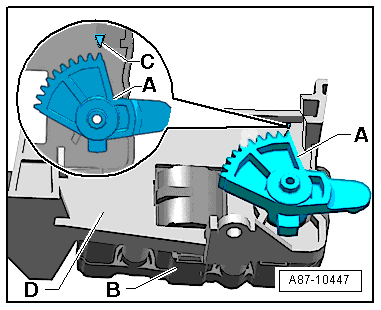
–  Check the position of the toothed segment -A-. The first tooth must be positioned as shown in relation to the mark -C-.
  Note
t  With a new replacement control motor, the shaft should always be positioned such that the toothed segment -A- can be attached as shown. If the control motor shaft is positioned such that the first tooth is not located as shown with respect to the mark -C- when attaching the toothed segment -A- (e.g. in the case of a control motor which has already been installed), the control motor must be connected to the vehicle electrical system and the temperature setting on the air conditioner operating and display unit, Climatronic control unit -J255- altered with the ignition switched on such that the control motor changes position and moves the toothed segment -A- to the correct position.
t  This control motor cannot be moved by applying a voltage. It only moves on being actuated by the air conditioner operating and display unit, Climatronic control unit -J255-.
  A87-10447
t  The toothed segment -A- (refer to top illustration), which is attached to the shaft of the control motor, has a larger tooth which must make contact during operation with the deeper tooth gap at the toothed segment -D- attached to the shaft of the temperature flap.
t  Depending on the production period, different toothed segments -A- are fitted (different design of connecting element to connecting rod for right temperature flaps) → Chapter and → Electronic parts catalogue
–  Fix the toothed segment -D- of the temperature flap in position with a pin -A- (diameter 4 mm) by way of the guide -B- and the mount -C-.
  A87-10448
–  Clip in the connecting rod -E- at the toothed segment -F-.
–  Plug in the connector -A-.
–  Insert the control motor with the corresponding holder -H- in the direction opposite to the arrow -arrow- in the mounts -C- and -D-.
–  Lay the wiring harness to the connector -A- such that it cannot come into contact with moving components (e.g. lever).
–  Fit the bolts -B-.
–  Re-install all the other parts removed in reverse order.
–  Switch on the ignition.
–  Perform air conditioner basic setting and final control diagnosis → "Guided fault-finding" function of vehicle diagnostic, testing and information system VAS 5051.
  Note
t  The control motors on this vehicle are equipped with electronics. A new control motor only learns its position at the air conditioning unit in the course of basic setting and can then be actuated by the air conditioner operating and display unit, Climatronic control unit -J255- (all control motors are identical at present) → "Guided fault-finding" function of vehicle diagnostic, testing and information system VAS 5051.
t  During basic setting, control motor assignment and adaption are implemented on the basis of the arrangement in the series connection of the wiring. If the sequence is not as specified, the matching of the control motors and thus flap control will not be correct → Chapter (block diagram of air conditioner control motors).
–  Interrogate the event recorder of the air conditioner operating and display unit, Climatronic control unit -J255- and erase any faults displayed → "Guided fault-finding" function of vehicle diagnostic, testing and information system VAS 5051.
  A87-10446

Removing and installing fresh air blower control unitJ126 > < Removing and installing air recirculation flap control motorV113