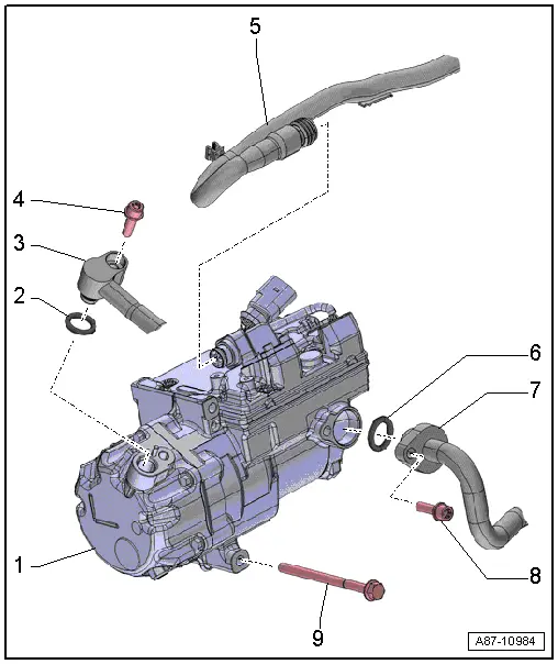
audi Workshop Repair Guides

Audi Workshop Service and Repair Manuals

Removing and installing electrically driven air conditioner compressor > < Removing and installing electrically driven air conditioner compressor (on vehicles with 4-cyl. engine)
Block diagram of electrically driven air conditioner compressor
  Note
t  With control unit for air conditioning compressor -J842- and electrical air conditioner compressor -V470-
t  If the control unit for air conditioning compressor -J842- is defective, the amount of refrigeration oil in the new air conditioner compressor must be adjusted. The refrigerant circuit does not have to be flushed with refrigerant R134a for this purpose → Air conditioner with refrigerant R134a.
t  For further information on the air conditioner compressor, refer to → Chapter and → Air conditioner with refrigerant R134a
   
1 - Electrically driven air conditioner compressor
q   With control unit for air conditioning compressor -J842- and electrical air conditioner compressor -V470-
q   → Chapter „Detaching electrically driven air conditioner compressor from holder/attaching“
q   → Chapter „Removing and installing electrically driven air conditioner compressor“
2 - O-ring
q   Replace
3 - Refrigerant line
q   High-pressure end
4 - Bolt
q   Tightening torque 9 Nm (for bolts with M 6 thread) and 25 Nm (for bolts with M 8 thread)
5 - High-voltage cable to power and control electronics for electric drive -JX1-
6 - O-ring
q   Replace
7 - Refrigerant line
q   Low-pressure end
8 - Bolt
q   Tightening torque 9 Nm (for bolts with M 6 thread) and 25 Nm (for bolts with M 8 thread)
9 - Bolt
q   Tightening torque 25 Nm


Removing and installing electrically driven air conditioner compressor > < Removing and installing electrically driven air conditioner compressor (on vehicles with 4-cyl. engine)