
A4 Mk3
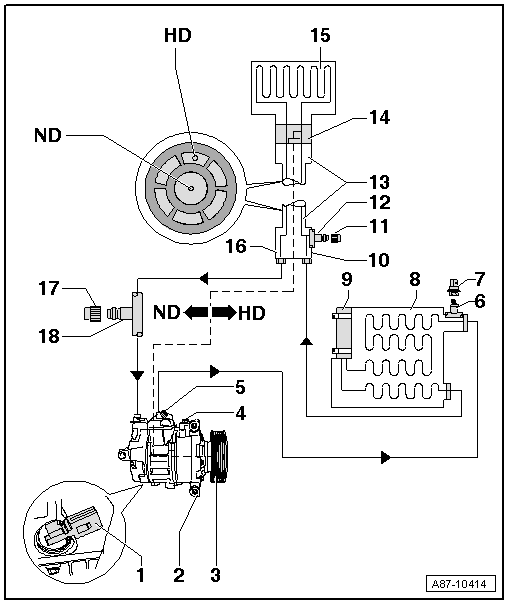
| 1 - | Air conditioner compressor regulating valve -N280- |
| q | Checking actuation and operation → Chapter1) |
| 2 - | Air conditioner compressor |
| q | Detaching air conditioner compressor from holder/re-attaching on vehicles with a 4-cyl. engine and a 6-cyl. TDI engine → Chapter1) |
 Note
Note| t | On vehicles with a 6-cyl. petrol or an 8-cyl. FSI engine, the air conditioner compressor can only be detached from the holder and removed after draining the refrigerant circuit → Chapter (Removing and installing air conditioner compressor). |
| t | The air conditioner compressors fitted at the start of production are manufactured by „Denso“ (type „6 SEU 14“) for vehicles with a 4 and 6-cyl. engine and type „7 SEU 17“ for vehicles with an 8-cyl. FSI engine). Different makes of air conditioner compressor may also be fitted at a later date → Electronic parts catalogue and → Air conditioner with refrigerant R134a. |
| t | The type of compressor may differ depending on the production period and engine. → Electronic parts catalogue |
| t | Not all replacement air conditioner compressors have the same oil capacity. Attention is therefore to be paid to the quantity of oil in the air conditioner compressor and the exact part number → Electronic parts catalogue and → Air conditioner with refrigerant R134a. |
| t | There may be different refrigeration oil capacities for the refrigerant circuit depending on the type of air conditioner compressor. The reason for the different oil quantities in the air conditioner compressor for an otherwise identical refrigerant circuit is the design of the actual air conditioner compressor. Attention is to be paid to these oil quantities. Too much oil in the refrigerant circuit results in higher pressures and a reduction in the cooling output of the air conditioner. Lubrication problems may be encountered in the air conditioner compressor if there is insufficient oil → Air conditioner with refrigerant R134a. |
| t | When installing the refrigerant lines and the corresponding holders, make sure there is sufficient distance between belt, holder and pulley. |
| t | As of Model Year 2012, certain vehicles with a 4-cyl. engine are gradually to be fitted with an air conditioner compressor additionally provided with an air conditioning system magnetic clutch -N25-. In certain air conditioner operating modes (e.g. „Econ“ mode), the air conditioner compressor drive system is completely deactivated by way of this magnetic clutch. For -N25- to be actuated by the operating and display unit, Climatronic control unit -J255-, the correct version of -J255- must be fitted and correctly encoded → Electronic parts catalogue and → Vehicle diagnostic, testing and information systemVAS 5051/, ”Guided fault-finding” function. |
| 3 - | Pulley / drive unit of air conditioner compressor / pulley with magnetic clutch -N25- |
| q | Air conditioner compressor pulley replacement. Applies to vehicles with a 4 and 6-cyl. engine 1) → Chapter. |
| q | Poly V-belt removal and installation. Applies to vehicles with a 4 and 6-cyl. engine 1) → Engine, mechanics; Rep. gr.19. |
| q | Poly V-belt assignment (for vehicles with a 4 and 6-cyl. engine) → Electronic parts catalogue |
| q | Air conditioner compressor drive unit replacement (vehicles with an 8-cyl. FSI engine) → Chapter (Removing air conditioner compressor → Chapter) |
| q | Replacement of pulley with magnetic clutch -N25-. Applies to certain vehicles with a 4-cyl. engine as of Model Year 20121) → Chapter |
Note| t | An overload safeguard is fitted between the pulley/drive unit and the drive shaft of the air conditioner compressor to protect the belt/drive unit if the air conditioner compressor becomes jammed or stiff. |
| t | If the air conditioner compressor is not operating smoothly, the overload safeguard interrupts power transmission to the air conditioner compressor. |
| t | Rubber elements are fitted between the pulley/drive unit and the air conditioner compressor drive shaft to cushion any vibration occurring during air conditioner compressor operation (damper function in the event of torque fluctuations). |
| t | The air conditioner compressor is fitted with different pulleys depending on the type of air conditioner compressor and engine → Electronic parts catalogue and → Chapter. |
| t | As of Model Year 2012, certain vehicles with a 4-cyl. engine are gradually to be fitted with an air conditioner compressor additionally provided with an air conditioning system magnetic clutch -N25-. In certain air conditioner operating modes (e.g. „Econ“ mode), the air conditioner compressor drive system is completely deactivated by way of this magnetic clutch. For -N25- to be actuated by the operating and display unit, Climatronic control unit -J255-, the correct version of -J255- must be fitted and correctly encoded → Electronic parts catalogue and → Vehicle diagnostic, testing and information systemVAS 5051/, ”Guided fault-finding” function. |
| 4 - | Oil drain plug |
| 5 - | Pressure relief valve |
| 6 - | Connection with valve |
| 7 - | Refrigerant pressure and temperature sender -G395-1) |
| q | Removing and installing → Chapter |
| q | For checking signal, refer to → Vehicle diagnostic, testing and information systemVAS 5051/, "Guided fault-finding" function |
Note| t | The refrigerant pressure and temperature sender -G395- uses a local data bus to exchange information with the onboard supply control unit -J519-. -J519- transmits the data via the data bus to the operating and display unit, Climatronic control unit -J255-. This vehicle is therefore not to be fitted with a high-pressure sender -G65- (only emits square-wave signals) → Electronic parts catalogue. |
| t | The temperature measured by the refrigerant pressure and temperature sender -G395- differs on account of the design of -G395- and its fitting location from the actual temperature of the refrigerant in the refrigerant circuit. At present this is therefore not evaluated and thus not used for air conditioner regulation. |
| 8 - | Condenser |
| q | Different versions → Electronic parts catalogue |
Note| Depending on the version of the radiator and condenser, it may be necessary (e.g. on the Audi RS 5) to drain the refrigerant circuit and detach the refrigerant lines from the condenser to detach the condenser from the front end or to remove the radiator → Chapter |
| 9 - | Receiver |
| q | The receiver is attached directly to the condenser → Chapter (removing and installing receiver) |
| q | Different versions → Electronic parts catalogue |
| 10 - | Quick-release coupling of refrigerant line - high-pressure end |
 WARNING
|
| 11 - | Cap |
| q | With seal |
| q | Always to be screwed on |
| 12 - | Service connection on high-pressure end |
| q | Different versions (with primary sealing valve or Schrader valve) depending on refrigerant line; distinguishing features → Air conditioner with refrigerant R134a |
| q | For air conditioner service station for measuring pressure and draining and filling refrigerant circuit → Air conditioner with refrigerant R134a |
| q | Depending on the engine version, certain components may have to be removed for connection of the service coupling. |
WARNING
|
Note| Depending on the position of the service connection at the refrigerant line and the vehicle model, it may be necessary to remove the additional body brace stiffener on the left to permit connection of the service coupling of the air conditioner service station (e.g. on the Audi Q5) → Running gear; Rep. gr.40 and → Air conditioner with refrigerant R134a |
| 13 - | Refrigerant line with internal heat exchanger |
| q | In this refrigerant line, the hot liquid refrigerant flowing on the high-pressure end supplies energy to the cold refrigerant vapour flowing on the low-pressure end, thus enhancing the efficiency of the air conditioner. |
| 14 - | Expansion valve |
| 15 - | Evaporator |
| 16 - | Quick-release coupling of refrigerant line - low-pressure end |
WARNING
|
| 17 - | Cap |
| q | With seal |
| q | Always to be screwed on |
| 18 - | Service connection on low-pressure end |
| q | Different versions (with primary sealing valve or Schrader valve) depending on refrigerant line; distinguishing features → Air conditioner with refrigerant R134a |
| q | For air conditioner service station for measuring pressure and draining refrigerant circuit → Air conditioner with refrigerant R134a |
| q | Depending on the engine version, certain components may have to be removed for connection of the service coupling. |
WARNING
|
Note| Depending on the position of the service connection at the refrigerant line and the vehicle model, it may be necessary to remove the additional body brace stiffener on the left to permit connection of the service coupling of the air conditioner service station (e.g. on the Audi Q5) → Running gear; Rep. gr.40 and → Air conditioner with refrigerant R134a |