audi Workshop Repair Guides

Audi Workshop Service and Repair Manuals

O-rings for refrigerant circuit > < Removing and installing refrigerant pressure and temperature senderG395, checking signal
Checking pressure signal at refrigerant pressure and temperature senderG395
Checking pressure signal at refrigerant pressure and temperature sender -G395-
  Note
t  The cooling output cannot be checked with the refrigerant pressure and temperature sender -G395- removed; the operating and display unit, Climatronic control unit -J255- does not switch on the air conditioner compressor → Vehicle diagnostic, testing and information systemVAS 5051/, "Guided fault-finding" function.
t  For checking the measured values of the refrigerant pressure and temperature sender -G395-, refer to → Vehicle diagnostic, testing and information systemVAS 5051/, "Guided fault-finding" function.
t  
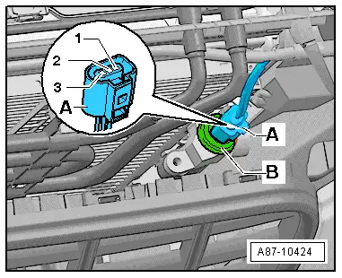
The refrigerant pressure and temperature sender -G395- uses a local data bus to exchange information with the onboard supply control unit -J519-. -J519- transmits the data via the data bus to the operating and display unit, Climatronic control unit -J255-.
t  On account of the design of the refrigerant pressure and temperature sender -G395- and its fitting location, the temperature measured by the refrigerant pressure and temperature sender -G395- differs from the actual temperature of the refrigerant. At present this is therefore not evaluated or used for air conditioner regulation.
t  This vehicle is only to be fitted with a refrigerant pressure and temperature sender -G395- → Electronic parts catalogue.
t  After switching off the air conditioner compressor, a relatively long period may elapse with this vehicle before the pressure on the high-pressure end decreases (the expansion valve is „cold“ and the pressure on the low-pressure end increases rapidly after switch-off, the expansion valve closes and the refrigerant can only flow slowly to the low-pressure end).
Preparation
–  Switch off the ignition.
–  Remove the upper cover for the lock carrier → General body repairs, exterior; Rep. gr.50.
   
–  Unplug the connector -A-.
Assignment of 3-pin connector at refrigerant pressure and temperature sender -G395--A-
1 - Earth
2 - Signal output – via local data bus to onboard supply control unit -J519-
3 - Terminal „75“ (positive)
Test sequence:
–  Switch on the ignition.
–  Check the earth and positive connection to the connector -A-.
–  Check the connection and operation of the refrigerant pressure and temperature sender -G395- as described in the guided fault-finding → Vehicle diagnostic, testing and information systemVAS 5051/, "Guided fault-finding" function.
  Note
t  When the connector -A- is unplugged, the air conditioner compressor (air conditioner compressor regulating valve -N280-) is not actuated.
t  The refrigerant pressure and temperature sender -G395- is an electronic control unit which exchanges information via a local data bus with the onboard supply control unit -J519- → Vehicle diagnostic, testing and information systemVAS 5051/, "Guided fault-finding" function.
  A87-10424

O-rings for refrigerant circuit > < Removing and installing refrigerant pressure and temperature senderG395, checking signal